Map Examples
This section provides the following map examples:
Example: How to Create a Simple Map
In this example, a few simple maps and illustrated to show how to create and display the packet distribution in place on the node.
When you set up flow maps from the perspective of your tools, start by asking yourself which traffic you would like a particular tool to see. Then, select the necessary traffic from network ports.
For example, the scenario in this example is as follows:
|
•
|
An application performance management tool is connected to tool port 2/4/x6 that focuses on traffic from VLANs 100..199 on network ports 2/2/x10 and 2/2/x12. |
|
•
|
An application performance Management tool connected to tool port 2/4/x18 that focuses on traffic from VLANs 200..299 on network ports 2/2/x10 and 2/2/x12. |
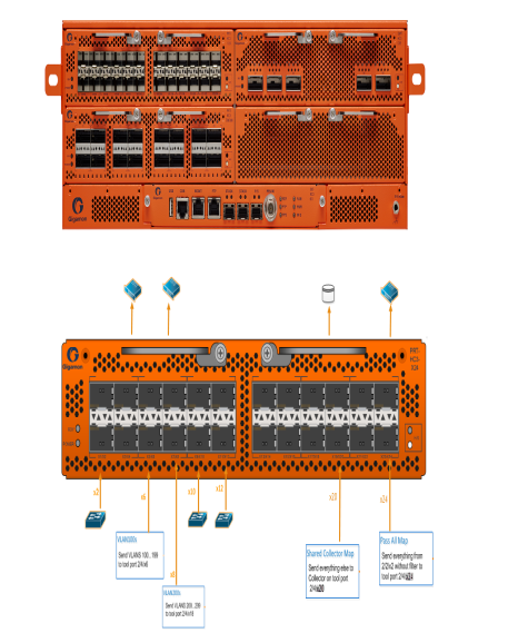
The packet distribution of for this scenario is illustrated in Figure 1: Graphical representation of Sample Maps.

|
Figure 43
|
Graphical representation of Sample Maps |
In the example shown in Figure 1: Graphical representation of Sample Maps, the configuration is as follows:
|
•
|
BoxID for the GigaVUE-HC3 is set as 2. |
|
•
|
The network ports are set on the second blade in the. |
|
•
|
The tool ports are set on the fourth blade in the node. |
Therefore, the ports in this scenario are represented as follows:
|
•
|
The network port IDs are set as 2/2/x2, 2/2/x10, and 2/2/x12. |
|
•
|
The tool port IDs are set as 2/4/x6, 2/4/x8, 2/2/x20, and 2/4/x24 |
The maps for this scenario the map types are set as follows:
|
•
|
The maps with the VLAN rules specified have the subtype set as By Rule. |
|
•
|
The shared collector maps are set as subtype Collector and no rules added. |
|
•
|
The passall maps are defined as subtype Pass All and no rules added. |
For details about the different map types, refer toMatrix of Map Types and Map Subtypes.
Except for the following map types, the map type defaults to Regular
|
•
|
Only maps with inline bypass solutions can be set as type Inline. |
|
•
|
Only maps that have GigaSMART operations defined for second level maps can be set as First Level or Second Level maps. |
The following are the steps to create the simple maps as shown in Figure 1: Graphical representation of Sample Maps:
|
1.
|
Check the port types for the each of the ports that the maps will use and set them if necessary. |
To set the port types, select Port > Ports > All Ports and use the Port Type Editor to set the port types. For more information about port types, refer to

|
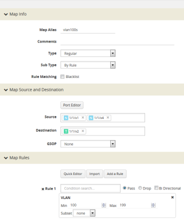
Figure 44
|
Map for VLAN 100..199 |
|
3.
|
Create a Regular map with a By Rule subtype to pass the VLAN200 traffic. |
|
4.
|
Create a map with type Regular and subtype Collector to create a shared collector map. For more information about shared collector maps, refer to About Shared Collectors. |
|
5.
|
Create a map with type Regular and subtype Pass All to create the passall map. |
Example: How to Handle Overlaps when Sending VLANs and Subnets to Different Tools
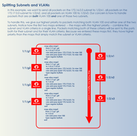
Figure 3: Sending Subnets and VLANs to Different Ports shows how to use map priority when handling packets matching criteria in multiple maps. In this example, we want to achieve the following results:
|
•
|
Send packets on the 172.16.0.0 subnet to 1/2/x1 |
|
•
|
Send packets on the 172.17.0.0 subnet to 1/2/x2 |
|
•
|
Send packets on VLAN 100 to 1/2/x3 |
The trick is in how to handle packets on either 172.16.0.0 or 172.17.0.0 and VLAN 100. In this example, we use map priority to ensure that packets such as this are sent to both of their desired destinations.
Notice that the first two maps configured in Figure 3: Sending Subnets and VLANs to Different Ports are set up to handle this situation. For example, map1 has a pass rule that accepts packets on 172.16.0.0 and VLAN 100. It sends matching packets to both 1/2/x1 (the destination we wanted for the 172.16 subnet) and 1/2/x3 (the destination we wanted for VLAN 100). Because this map was entered before map3, it has higher priority, ensuring the packet goes to both 1/2/x1 and 1/2/x3 and not just the 1/2/x3 destination specified by map3.
The same principle is applied in map2 for packets on 172.17.0.0 and VLAN 100.
Note: If we did not observe the order of map entry shown in Figure 3: Sending Subnets and VLANs to Different Ports, we could always adjust the priority as needed using the instructions in Example: How to Create a Simple Map.

|
Figure 45
|
Sending Subnets and VLANs to Different Ports |


