GigaSMART Layer 2 GRE Tunnel Encapsulation/Decapsulation
Required License for L2GRE Decapsulation: Base (GigaVUE-HC2, and GigaVUE-HC3), Tunneling (GigaVUE‑HC1)
Required License for L2GRE Encapsulation: Advanced Tunneling (GigaVUE-HC2, and GigaVUE-HC3), Tunneling (GigaVUE‑HC1)
Use GigaSMART Layer 2 (L2) Generic Routing Encapsulation (GRE) tunnel encapsulation to send traffic from one GigaSMART node over the Internet to a second GigaSMART node using L2GRE encapsulation. Use GigaSMART L2GRE tunnel decapsulation at the second GigaSMART node to decapsulate the traffic before sending it to local tool ports.
GigaSMART Layer 2 GRE tunnel encapsulation/decapsulation provides the following:
|
•
|
L2GRE tunnel initiation and encapsulation on the tool port at the sending end of the tunnel (for example, at a remote site) |
|
•
|
L2GRE tunnel termination and decapsulation on the network port at the receiving end of the tunnel (for example, at a main office site) |
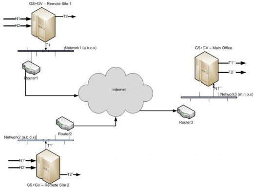
The GigaSMART at the remote site encapsulates the filtered packets, adds an encapsulation header, and routes it to the main office site. The encapsulation protocol is GRE and the delivery protocol is IP or IPv6, so the encapsulation header consists of Ethernet + IP + GRE or Ethernet + IPv6 + GRE headers.
The parameters of the encapsulated header are user-configurable, such as the IPv4 address of the IP interface on the destination GigaSMART node and the GRE key that identifies the source of the tunnel.
At the remote end, packets are decapsulated, the L2GRE header is stripped off, and packets are sent to the specified tool port.
IP fragmentation and reassembly are supported. Refer to IP Fragmentation and Reassembly on L2GRE and GMIP Tunnels.
Figure 1 L2GRE Tunnel Encapsulation/Decapsulation shows the remote site encapsulating the filtered traffic and routing it to the main office from the remote end.
The encapsulated packet is sent out of the tool port, which is connected to the public network (the Internet). This packet is routed in the public network to reach the main office site. It ingresses at the routed network port of the GigaVUE node at the main office.
The ingress encapsulated packet is then sent to the GigaSMART at the main office, where the packet is decapsulated and sent to the tool port. The received packet’s destination IP is checked against the source IP/IPv6 configured for the network port. If they match, decapsulation is applied. The Ethernet + IP + GRE or Ethernet + IPv6 + GRE header is stripped and the remaining packet is sent to the tool port.
|
Figure 128
|
L2GRE Tunnel Encapsulation/Decapsulation |
For L2GRE tunnel encapsulation/decapsulation configuration examples, refer to Example 1 – GigaSMART L2GRE Tunnel Encapsulation and Example 4 – GigaSMART L2GRE Tunnel Decapsulation.
For statistics for encapsulated packets, refer to Display L2GRE Tunnel Encapsulation Statistics. For statistics for decapsulated packets, refer to Display L2GRE Tunnel Decapsulation Statistics.
Layer 2 GRE Header Length
The L2GRE header length is as follows:
|
Header
|
Length in Bytes
|
|
With Key
|
42 bytes consisting of 14 Ethernet + 20 IP + 4 GRE + 4 GRE Key.
|
|
Without Key
|
38 bytes consisting of 14 Ethernet + 20 IP + 4 GRE.
|
Load Balancing to Multiple Destinations
Starting in software version 5.1, L2GRE tunnel encapsulation supports load balancing. Traffic from an IP Interface can be sent to multiple destinations Defined by IP address. The traffic is distributed using stateful load balancing or stateless hashing.
For information on stateful and stateless load balancing, refer to GigaSMART Load Balancing.
For examples of load balancing on L2GRE encapsulation, refer to Example 2 – GigaSMART L2GRE Tunnel Encap Stateful LB and Example 3 – GigaSMART L2GRE Tunnel Encap Stateless LB.
L2GRE IPv6 Encapsulation/Decapsulation
Gigasmart L2GRE IPv6 lets you route filtered traffic to the remote
end using IPv6-based L2GRE tunneling. At the receiving end, filtered traffic is sent to
GigaSMART, which adds an L2GRE header and a IPv6 header to make it routable.
The remote end decapsulates the packet and sends it to the tool port.
GigaVUE nodes act as L2GRE encapsulation and decapsulation devices.
The IPv6 protocol is used to deliver all packets received in the encap tunnel to the
termination node using the configured source and destination IPv6 address. The tunnel
termination (decap) node strips the IPv6 + GRE header and sends the payload to the tool port.
The ICMPv6 protocol is used by the tool port on the encapsulation node for Neighbor
Solicitation (NS) and Neighbor Advertisement (NA) messages to resolve the gateway
MAC address and respond to NS messages received from the gateway in the tunnel
decapsulation/termination node. ICMPv6 echo request/reply messages are also sent and received.
For a configuration example, refer to Example 5 – GigaSMART L2GRE IPv6 Tunnel Encamp/Decap with Load-Balancing
L2GRE Tunnel Termination
L2GRE tunnel termination is supported on physical devices, and the decapsulation happens through the GigaSMART engine. Tunneled traffic coming in the chassis is sent to the GigaSMART engine, which is sent to the tools using a hybrid port. The maps created are then applied to this decapsulated traffic.
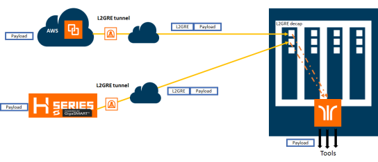
Starting with version 5.4, tunnel termination is supported for VXLAN and L2GRE tunnel in the front panel ports of the switch. This feature provides line rate tunneling on all faceplate ports and also allows flow mapping to be applied for the incoming tunneled traffic on the same ports.
The following diagram illustrates how the traffic from two sources—a GigaVUE V Series appliance running on an AWS platform and a GigaVUE H Series device at a remote site traverses through the L2GRE tunnel and reaches the GigaVUE-H Series node in the main office site. In each case, traffic is tapped at the remote source and is then tunneled through L2GRE encapsulation across the cloud before it reaches the GigaVUE H Series device at the main office site, which is connected to the actual tools. The L2GRE tunnel termination is executed on an ingress circuit port (IP interface) on the destination GigaVUE H Series device. After tunnel termination, the packet is presented to the flow mapping module to filter based on map rule parameters.
Configure L2GRE Tunnel Encapsulation and Decapsulation
Refer to the following configuration examples:
Configure GigaSMART Operation for Layer 2 GRE
To access GigaSMART within GigaVUE-FM, access a device that has been added to GigaVUE-FM from the GigaVUE-FM interface. GigaSMART appears in the navigation pane of the device view on supported devices. Refer to Access GigaSMART from GigaVUE-FM for details.
To configure the L2GRE encapsulation/decapsulation types and options, use the GigaSMART Operations (GSOP) page:
|
1.
|
From the device view, select GigaSMART > GigaSMART Operations (GSOP) > GigaSMART Operation. |
|
3.
|
On the GigaSMART Operations page, do the following: |
|
a.
|
Type an alias in the Alias field. |
|
b.
|
In the GigaSMART Groups field, select the gsgroup for this operation. |
|
c.
|
In the GigaSMART Operations (GSOP) field, select either Tunnel Decapsulation or Tunnel Encapsulation from the drop-down list, depending on whether you want decapsulation or encapsulation. |
|
d.
|
Select L2GRE, and then enter options in the fields that display. |
Example 1 – GigaSMART L2GRE Tunnel Encapsulation
In this example, an IP interface is configured on the tool port. A GigaSMART operation for tunnel encapsulation is configured to encapsulate the filtered packets. A map is configured that uses the L2GRE tunnel encapsulation GigaSMART operation, which sends packets from the remote site over the Internet to the main office using the IP interface associated with a tool port. Staring with software version 5.4 GigaSMART L2GRE Tunnel Encapsulation provides support for IPv6 with load-balancing.
|
Task
|
Description
|
UI Steps
|
|
|
Configure a tool type of port and a network type of port.
|
|
a.
|
Select Ports > All Ports. |
|
b.
|
Click Quick Port Editor. |
|
c.
|
Use Quick search to find the ports to configure. |
|
d.
|
Set the type (Network or Tool) for each port and select Enable. |
|
|
|
Configure a GigaSMART group and associate it with a GigaSMART engine port.
|
|
a.
|
From the device view, select GigaSMART > GigaSMART Groups. |
|
c.
|
Type an alias in the Alias field and enter an engine port in the Port List field. |
|
|
|
Configure the IP interface with an IP address, subnet mask, default gateway, and MTU setting. Assign it to the GigaSMART group.
|
|
a.
|
Select Ports > Ports > IP Interfaces. |
|
c.
|
On the IP Interfaces page, in the Alias and Comment fields, enter a name and description for the IP interface. |
|
d.
|
Click the Ports field and select the network or tool port from the drop-down list. |
|
e.
|
Select Type: IPv4 or IPv6 |
|
f.
|
Enter the IP address, subnet mask, gateway, and MTU settings in the respective fields. |
|
g.
|
Click on the GigaSMART Group field to select the GigaSMART group. |
|
|
|
Configure the GigaSMART operation for tunnel encapsulation and assign it to the GigaSMART group. The tunnel encapsulation settings include the IP address (IPv4) of the IP interface on the destination GigaSMART node and the GRE key that identifies the source of the tunnel.
|
|
a.
|
From the device view, select GigaSMART > GigaSMART Operations > GigaSMART Operation. |
|
c.
|
Type an alias in the Alias field. |
|
d.
|
From the GigaSMART Groups drop-down list, select the GigaSMART Group that you created in the second task. |
|
e.
|
From the GigaSMART Operations (GSOP) drop-down list select Tunnel Encapsulation. |
|
f.
|
Select L2GRE for the encapsulation type. |
|
g.
|
Enter the IP address of the IP interface in the Destination IP field. |
|
h.
|
IPv4, iPv6 or Port Group |
|
i.
|
Enter the key parameter in the Key field. |
|
|
|
Create a map using the tunnel encapsulation GigaSMART operation, with packets coming from the network port and being sent to the Internet through the tool port.
|
|
c.
|
Type an alias in the Map Alias field that will help you identify this map. |
|
d.
|
Select Regular for Type and By Rule for Subtype. |
|
e.
|
Specify the network and tool ports that you configured in task one in the Source and Destination fields, respectively. |
|
f.
|
From the GigaSMART Operations (GSOP) drop-down list, select the GigaSMART operation configured in task 4. |
|
g.
|
Click Add a Rule under Map Rules and create the following rule: |
Select IP Version from the drop-down list and select v4 for Version, and then select Pass.
|
Example 2 – GigaSMART L2GRE Tunnel Encap Stateful LB
Example 2 configures stateful load balancing of tunnel traffic to tunnel endpoints based on a metric. Each tunnel endpoint is assigned a weight.
To access GigaSMART within GigaVUE-FM, access a device that has been added to GigaVUE-FM from the GigaVUE-FM interface. GigaSMART appears in the navigation pane of the device view on supported devices. Refer to Access GigaSMART from GigaVUE-FM for details.
To configure this example:
|
1.
|
Go to Ports > Ports > All Ports. Make sure you have one tool type of port and one network type of port enabled. Also make sure you have a GigaSMART port (eport). |
|
2.
|
Go to GigaSMART > GigaSMART Groups. |
|
3.
|
Click New, and then configure an Alias for the GigaSMART group and associate it with a GigaSMART engine port. |
|
5.
|
Go to Ports > Ports > IP Interfaces. |
|
6.
|
Click New, and then in the Alias and Comment fields, enter the alias and description of the IP interface. |
|
7.
|
Select a port and configure it with an IP version Type, IP Address, IP Mask, Gateway, and MTU. Assign the IP interface to the GigaSMART group. |
|
9.
|
Go to Ports > Tunnel Endpoints. |
|
10.
|
Click New, then configure one or more tunnel endpoint IDs and their IP Addresses. The Alias is optional. |
|
12.
|
Go to Ports > Port Groups. |
|
13.
|
Click New, then type an alias for the port group, select GigaSMART Load Balancing, select the previously configured tunnel endpoints. Optionally, you can specify weights for each tunnel endpoint in the port group. |
|
15.
|
Go to GigaSMART > GigaSMART Operations (GSOP) > GigaSMART Operation. |
|
16.
|
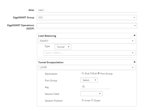
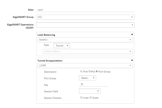
Click New, then select the same GigaSMART Group and Tunnel Encapsulation for the GSOP. Under Load Balancing, select Stateful, the type Tunnel, and the metric, such as Round Robin. Under Tunnel Encapsulation, select L2GRE, Destination Port Group, select the Port Group, Session Field, and Session Position. Refer to Figure 2 New GigaSMART Operation for Stateful Load Balancing. |
|
Figure 129
|
New GigaSMART Operation for Stateful Load Balancing |
|
19.
|
Click New, then type an alias for the map, select type Regular and subtype ByRule. Under Map Source and Destination, select a network port as the Source and a tool port as the Destination, then select the GigaSMART operation. Under Map Rules, configure a map rule. Refer to Figure 3 New Map Configuration. |

|
Figure 130
|
New Map Configuration |
Example 3 – GigaSMART L2GRE Tunnel Encap Stateless LB
Example 3 configures stateless load balancing of tunnel traffic to tunnel endpoints based on a hash value.
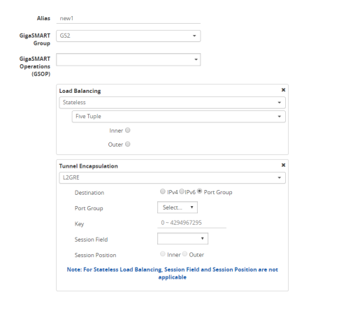
Example 3 has the same configuration steps as Example 2 except for the GigaSMART operation (gsop) in Step 16. Under Load Balancing, select Stateless and the metric, such as Five Tuple. Under Tunnel Encapsulation, select L2GRE, Destination Port Group, and select the Port Group. Refer to Figure 4 New GigaSMART Operation for Stateless.
|
Figure 131
|
New GigaSMART Operation for Stateless |
Example 4 – GigaSMART L2GRE Tunnel Decapsulation
In this example, an IP interface is configured on the network port. A GigaSMART operation for tunnel decapsulation is configured to decapsulate the filtered packets. A map is configured that uses the L2GRE tunnel decapsulation GigaSMART operation, which receives packets from the remote site over the Internet to the main office using the IP interface associated with a tool port and then forwards packets over the tool port. Staring with software version 5.4 GigaSMART L2GRE Tunnel Decapsulation provides support for IPv6 with load-balancing.
|
Task
|
Description
|
UI Steps
|
|
|
Configure a network type of port and a tool type of port.
|
|
a.
|
Select Ports > Ports > All Ports. |
|
b.
|
Click Quick Port Editor. |
|
c.
|
Use Quick search to find the ports to configure. |
|
d.
|
Set the type for each port and select Enable. |
|
|
|
Configure a GigaSMART group and associate it with a GigaSMART engine port.
|
|
a.
|
From the device view, select GigaSMART > GigaSMART Groups. |
|
c.
|
Type an alias in the Alias field and enter an engine port in the Port List field. |
|
|
|
Configure the IP interface with an IP address, subnet mask, default gateway, and MTU setting. Assign it to the GigaSMART group.
The IP address must match the destination IP address specified at the sending end of the tunnel.
|
|
a.
|
Select Ports > IP Interfaces. |
|
c.
|
On the IP Interfaces page, in the Alias and Comment fields, enter the name and description for the IP interface. |
|
d.
|
Click the Ports field and select the port from the drop-down list. |
|
e.
|
Enter the IP address, subnet mask, gateway, and MTU settings in the respective fields. |
|
f.
|
Click on the GigaSMART Group field to select the GigaSMART group. |
|
|
|
Configure the GigaSMART operation for tunnel decapsulation and assign it to the GigaSMART group. The tunnel decapsulation settings include the GRE key that identifies the source of the tunnel.
|
|
a.
|
From the device view, select GigaSMART > GigaSMART Operations > GigaSMART Operation. |
|
c.
|
Type an alias in the Alias field. |
|
d.
|
From the GigaSMART Groups drop-down list, select the GigaSMART Group that you created in the second task. |
|
e.
|
From the GigaSMART Operations (GSOP) drop-down list select Tunnel Decapsulation. |
|
f.
|
Select L2GRE for the decapsulation type. |
|
g.
|
Enter the GRE key in the Key field. |
|
|
|
Create a map using the tunnel decapsulation GigaSMART operation, with packets coming from the Internet through the network port and being sent to the local tool port.
|
|
a.
|
Select Maps > Maps > Maps. |
|
c.
|
Type an alias in the Map Alias field that will help you identify this map. |
|
d.
|
Select Regular and By Rule for the map type and subtype. |
|
e.
|
Specify the network and tool ports that you configured in task one in the Source and Destination fields, respectively. |
|
f.
|
From the GSOP drop-down list, select the GigaSMART operation configured in task 4. |
|
g.
|
Click Add a rule under Map Rules and create the following rule: |
Select IP Version from the drop-down list and select v4 for Version, and then select Pass.
|
Example 5 – GigaSMART L2GRE IPv6 Tunnel Encamp/Decap with Load-Balancing
In this example, the encapsulation and decapsulation nodes are configured with IP interfaces using IPv6 addresses and load-balancing. IPv6 tunnel load-balancing feature supports the distribution of traffic across multiple IPv6 tunnel destination through the same tool port. Two types of load-balancing is supported, stateful and stateless.
To access GigaSMART within GigaVUE-FM, access a device that has been added to GigaVUE-FM from the GigaVUE-FM interface. GigaSMART appears in the navigation pane of the device view on supported devices. Refer to Access GigaSMART from GigaVUE-FM for details.
Step 1: Configure a tool type of port and a network type of port.
Create a map using the tunnel encapsulation GigaSMART operation, with packets coming from the network port and being sent to the Internet through the tool port.
|
1.
|
Select Ports > Ports > All Ports. |
|
2.
|
Click Quick Port Editor. |
|
3.
|
Use Quick search to find the ports to configure. |
|
4.
|
Set the type for each port and select Enable. |
|
a.
|
type: tool - port 1/3/x7 |
|
b.
|
type: network - 1/3/x8 |
Step 2: Configure a GigaSMART group and associate it with a GigaSMART engine port.
|
1.
|
From the device view, select GigaSMART > GigaSMART Groups. |
|
3.
|
Type an alias in the Alias field and enter an engine port in the Port List field. |
Step 3: Configure the IP Interface
|
1.
|
Select Ports > IP Interfaces. |
|
3.
|
In the Alias and Comment fields, enter the name and description for the IP interface. |
|
4.
|
Click the Ports field and select the port from the drop-down list. |
|
5.
|
Select the Port address: IPv6 |
|
6.
|
Enter the IP address, subnet mask, gateway, and MTU settings in the respective fields. |
|
7.
|
From the GS Group drop-down list, select the required GigaSMART group. |
Step 4: Configure the GigaSMART operation for tunnel encapsulation and load balancing and assign it to the GigaSMART group
|
1.
|
From the device view, select GigaSMART > GigaSMART Operations > GigaSMART Operation. |
|
Figure 132
|
GigaSMART Operation (GSOP) |
|
3.
|
In the Alias field, enter a name for the GigaSMART operation. |
|
4.
|
From the GigaSMART Group drop-down list, select the GigaSMART Group that you created in the step 2. |
|
5.
|
From the GigaSMART Operations (GSOP) drop-down list, select Tunnel Encapsulation. |
|
6.
|
Select L2GRE for the encapsulation type. |
|
7.
|
Enter the GRE key 123214 in the Key field. |
Step 5: Create a map using the tunnel encapsulation GigaSMART operation
|
1.
|
Select Maps > Maps > Maps. |
|
Figure 133
|
Map Configuration |
|
3.
|
Type an alias in the Map Alias field that will help you identify this map. |
|
4.
|
Select Regular and By Rule for the map type and subtype. |
|
5.
|
Specify the network and tool ports that you configured in step one in the Source and Destination fields, respectively. |
|
6.
|
From the GSOP drop-down list, select the GigaSMART operation configured in step 4. |
|
7.
|
Click Add a rule under Map Rules. |
|
8.
|
Select IP Version from the drop-down list and select v4 for Version. |
|
10.
|
Click Add a rule under Map Rules and create the following rule: |
|
11.
|
Select IP Version from the drop-down list and select v6 for Version. |
|
b.
|
Destination: To: 1/4x7 |
On the decapsulation node, configure the receiving end of the tunnel
Step 6: Configure a tool type of port and a network type of port.
|
1.
|
Select Ports > Ports > All Ports. |
|
2.
|
Click Quick Port Editor. |
|
3.
|
Use Quick search to find the ports to configure. |
|
4.
|
Set the type for each port and select Enable. |
|
a.
|
type: tool - port 1/4/x7 |
|
b.
|
type: network - 1/4/x24 |
Step 7: Configure a GigaSMART group and associate it with a GigaSMART engine port.
|
1.
|
From the device view, select GigaSMART > GigaSMART Groups. |
|
3.
|
Type an alias in the Alias field and enter an engine port in the Port List field. |
Step 8: Configure the IP Interface with an IPv6 address, prefix length, default gateway, and MTU setting. Assign it to the GigaSMART group.
|
1.
|
Select Ports > IP Interfaces. |
|
3.
|
In the Alias and Comment fields, enter the name and description for the IP interface. |
|
4.
|
Click the Ports field and select the port from the drop-down list. |
|
5.
|
Enter the IP address, subnet mask, gateway, and MTU settings in the respective fields. |
|
6.
|
From the GS Group drop-down list, select the required GigaSMART group. |
Step 9: Configure the GigaSMART operation for tunnel decapsulation and assign it to the GigaSMART group.
|
1.
|
From the device view, select GigaSMART > GigaSMART Operations > GigaSMART Operation. |
|
3.
|
In the Alias field, enter a name for the GigaSMART operation. |
|
4.
|
From the GigaSMART Groups drop-down list, select the GigaSMART Group. |
|
5.
|
From the GigaSMART Operations (GSOP) drop-down list, select Tunnel Decapsulation. |
|
6.
|
Select L2GRE for the decapsulation type. |
|
7.
|
Enter the GRE key in the Key field. |
Step 10: Create a map using the tunnel decapsulation GigaSMART operation.
|
1.
|
Select Maps > Maps > Maps. |
|
3.
|
Type an alias in the Map Alias field that will help you identify this map. |
|
4.
|
Select Regular and By Rule for the map type and subtype. |
|
5.
|
Specify the network and tool ports that you configured in task one in the Source and Destination fields, respectively. |
|
6.
|
From the GSOP drop-down list, select the GigaSMART operation. |
|
7.
|
Click Add a rule under Map Rules and create the following rule: |
|
8.
|
Select IP Version from the drop-down list and select v4 for Version. |
|
10.
|
Click Add a rule under Map Rules and create the following rule: |
|
11.
|
Select IP Version from the drop-down list and select v6 for Version. |
|
b.
|
Destination: To: 1/4x7 |
Display L2GRE IPv6 Tunnel Statistics
To view IP Interfaces statistics, select Ports > IP Interfaces > Statistics to open the IP Interfaces Statistics page.
The IPv6 tunnel statistics pane displays the gateway status as Reachable if neighbor discovery is completed with gateway or Unreachable if neighbor discovery failed. Neighbor discovery is done only on the encapsulation node. On the decapsulation node, the gateway status will be Not Applicable.
Display L2GRE Tunnel Encapsulation Statistics
To display Layer 2 GRE tunnel encapsulation statistics, select GigaSMART > GigaSMART Operations (GSOP) > Statistics. The statistics for tunnel encapsulation will be in the row labeled Tunnel Encap in the GS Operations column.
Refer to Tunnel Encapsulation Statistics Definitions for descriptions of these statistics as well as to GigaSMART Operations Statistics Definitions.
Display L2GRE Tunnel Decapsulation Statistics
To display Layer 2 GRE tunnel decapsulation statistics, select GigaSMART > GigaSMART Operations (GSOP) > Statistics and click on the GS Operation in table to open the Quick View for GS Operation Statistics.
Refer to Tunnel Decapsulation Statistics Definitions for descriptions of these statistics as well as to GigaSMART Operations Statistics Definitions.


