GigaSMART IP Encapsulation/Decapsulation (GigaSMART Tunnel)
Required License for IP Decapsulation: Base (GigaVUE-HC2, and GigaVUE-HC3), Tunneling (GigaVUE‑HC1)
Required License for IP Encapsulation: Advanced Tunneling (GigaVUE-HC2, and GigaVUE-HC3), Tunneling (GigaVUE‑HC1)
Use GigaSMART encapsulation and decapsulation operations to send traffic arriving on one GigaSMART-enabled node over the Internet to a second GigaSMART-enabled node. There, the traffic is decapsulated and made available to local tool ports.
This feature is useful when instrumenting remote data centers – you can tunnel selected portions of the traffic from the remote GigaSMART-enabled node to tools in a central location. Traffic is encapsulated at the sending end of the tunnel and decapsulated at the receiving end.
IP fragmentation and reassembly are supported. Refer to IP Fragmentation and Reassembly on L2GRE and GMIP Tunnels.
The source of the GigaSMART tunnel can be any of the following:
|
•
|
GigaSMART-Enabled GigaVUE H Series Node
|
|
•
|
Standalone GigaVUE-HC3 node with SMT-HC3-C05 modules installed. |
|
•
|
Standalone GigaVUE-HC2 node with GigaSMART-HC0 front and/or rear modules installed. |
|
•
|
Standalone GigaVUE‑HC1 nodes. |
|
•
|
Any GigaVUE H Series node operating in a cluster with the previous node types. |
|
•
|
GigaVUE-2404 G Series node with a GigaSMART-6X line card installed
|
|
•
|
GigaVUE V Series node or a GigaVUE-VM |
Note: You can also create GigaSMART operations that allow a GigaVUE H Series node to act as the receiving end of an ERSPAN tunnel for data mirrored over the Internet from Cisco equipment. However, this feature requires the Advanced Tunneling license; refer to GigaSMART ERSPAN Tunnel Decapsulation.
Configure Both Ends of GigaSMART Tunnel
Creating a GigaSMART tunnel requires configuration on both the sending and receiving ends:
|
Sending End of Tunnel
|
Receiving End of Tunnel
|
|
The sending end of a GigaSMART tunnel can be either a GigaVUE-VM deployment or a GigaSMART-enabled GigaVUE H Series or G Series node.
Sending Data from a GigaSMART-Enabled GigaVUE H Series Node
|
•
|
Configure an IP interface with an IP address, subnet mask, default gateway, MTU setting and assign it to a GigaSMART group. |
|
•
|
Create a GigaSMART operation with a tunnel-encap component. The encapsulation settings include the IP address and listening UDP port of the P interface that is associated with a network port on the destination GigaVUE H Series. |
|
•
|
Bind the GigaSMART operation to one or more network ports as part of a map. The network ports must be mapped to the IP interface associated with a tool port. |
Sending Data from GigaVUE-VM/GigaVUE-FM
When you provision a vMap for a GigaVUE-VM node in GigaVUE-FM, in addition to selecting the virtual traffic to be forwarded, you also specify the destination to which traffic should be tunneled with the following settings:
|
•
|
UDP IP – The IP address of the P interface that is associated with a network port on the receiving end of the tunnel. |
|
•
|
UDP Source Port – The source port from which traffic will be sent to the receiving end of the GigaSMART tunnel. |
|
•
|
UDP Destination Port – The listening UDP port at the destination end of the GigaSMART tunnel. |
Sending Data from GigaVUE-2404/GigaSMART-6X
|
•
|
Configure an IP interface with an IP address, subnet mask, default gateway, and MTU setting. Associate the IP interface with a tool port. |
|
•
|
Create a GigaSMART operation with an encapsulation component. The encapsulation settings include the IP address and listening UDP port of the IP interface thst is associated with network port on the destination GigaVUE G Series. |
|
•
|
Bind the GigaSMART operation to one or more network ports as part of a map rule with at least one regular map rule criterion. The network ports must be mapped to the IP interface associated with a tool port. |
|
|
•
|
Configure an IP interface with an IP address, subnet mask, and default gateway. The IP address must match the destination IP address specified at the sending end of the tunnel. |
|
•
|
Create a GigaSMART operation with a decapsulation component. The decapsulation settings include the same listening UDP port you specified as the destination port at the sending end of the tunnel. |
|
•
|
Bind the GigaSMART operation to the IP interface that is associated with a network port as part of a map that distributes arriving traffic to local tool ports for analysis with local tools. |
|
Keep in mind the following when configuring GigaSMART operations with encapsulation/decapsulation components:
|
Feature
|
Description
|
|
Viewing Statistics
|
Use the show tunneled-port commands to see statistics related to ongoing tunnel operations. Refer to View GigaSMART Statistics for more information.
|
|
Packet Order
|
Packer sequence is not preserved if the packets are reordered while traversing the Internet. The receiving GigaSMART delivers them in the same order received.
|
|
GMIP Header
|
The GMIP header is 46 bytes consisting of 14 Ethernet + 20 IP + 8 UDP + 4 tunnel version.
|
|
Tunnel Decap Type GMIP portdst
|
Use the GigaSMART Operations page to specify the UDP port on which the P interface that is associated with a network port on the receiving GigaVUE H Series is listening. Use this option when decapsulating traffic from a either GigaSMART-enabled node or a GigaVUE-VM deployment. The setting must match the configuration of the portdst configured on the sending end of the tunnel.
|
|
GigaSMART Engine Ports
|
GigaSMART operations with a tunnel component can be assigned to GigaSMART groups consisting of multiple GigaSMART engine ports. Refer to Groups of GigaSMART Engine Ports for more information.
|
Example: GigaSMART Encapsulation/Decapsulation (GigaVUE‑HC1 Node)
The following figures demonstrate how to create a sample IP tunnel between a sending GigaVUE‑HC1 in Reno and a receiving GigaVUE H Series cluster in San Francisco. First, the overall tunnel is summarized, followed by configuration descriptions for the sending and receiving ends.
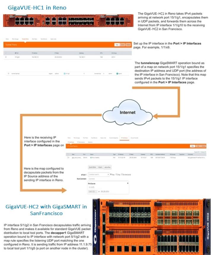
Configure Sending End of Tunnel: GigaVUE‑HC1 in Reno
The GigaVUE‑HC1 in this location has an IP interface configured on tool port 1/1/g1 with an IP address of 11.1.9.75. Maps to this port that use a tunnel encapsulation GigaSMART operation can send data over the Internet. The following table summarizes the commands necessary to configure the sending end of the tunnel in the CLI:
|
Task
|
UI Steps
|
|
Start by designating port 1/1/g1 as a tool port.
|
|
1.
|
Select Ports > Ports > All Ports. |
|
2.
|
Click Quick Port Editor. |
|
3.
|
In the Quick View Editor find port 1/1/g1. |
|
7.
|
Close the Quick Port Editor. |
|
|
Use the IP Interfaces page to set up the network parameters for 1/1/g1. This page sets the IP address, subnet mask, default gateway, and MTU for the IP interface associated with a tool port on port 1/1/g1. Notice that the GigaSMART group in this example has the alias gsport1.
|
|
1.
|
Select Ports > IP Interfaces. |
|
3.
|
Configure the IP interface: |
|
•
|
GigaSMART Group: gsport1 |
|
|
Now, create a tunnel encapsulation GigaSMART operation (tunnelencap) that will send traffic to IP address 21.2.9.75 on destination UDP port 10000 from source port 5000. The operation has the alias tunnelenc.
|
|
1.
|
From the device view, select GigaSMART > GigaSMART Operations (GSOP) > GigaSMART Operation. |
|
3.
|
Configure the GigaSMART Operation: |
|
•
|
GigaSMART Groups: gsport1 |
|
•
|
GigaSMART Operations (GSOP): Tunnel Encapsulation |
|
4.
|
Configure Tunnel Encapsulation: |
|
•
|
Port Destination: 10000 |
|
•
|
Destination IP: 21.2.9.75 |
|
|
Once you have the tunnel encapsulation operation, you can include it as part of a map rule. This map rule matches IPv4 packets and sends them to 21.2.9.75:10000 (the socket specified by the GigaSMART operation named tunnelencap that you created in the previous step).
|
|
1.
|
Select Maps > Maps > Maps |
|
•
|
GigaSMART Operations (GSOP): tunnelencap (gsport1) |
|
6.
|
Select IP Version for Rule 1. |
|
7.
|
Select v4 for Version. |
|
Configure Receiving End of Tunnel:
GigaVUE-HC2 with GigaSMART in San Francisco
Now we need to configure the receiving end of the tunnel with an IP interface associated with network port. The GigaVUE-HC2 in this location will have an IP interface associated with network port configured on network port 5/1/x2 with an IP address of 21.2.9.75 and a GigaSMART decapsulation operation that listens on UDP port 10000.
The following table summarizes the steps necessary to configure the receiving end of the tunnel using the UI:
|
Task
|
UI Steps
|
|
Start by designating port 5/1/x2 as a network port.
|
|
1.
|
Select Ports > Ports > All Ports. |
|
2.
|
Click Quick Port Editor. |
|
3.
|
In the Quick View Editor find port 5/1/x2. |
|
7.
|
Close the Quick Port Editor. |
|
|
Use the IP Interfaces page to set up the network parameters for 5/1/g2. This command sets the IP address, subnet mask, default gateway, and MTU for the IP interface associated with network port on port 5/1/g2. Note that this port uses the same IP address to which the GSOP in Reno is configured to send data (21.2.9.75).
|
|
1.
|
Select Ports > IP Interfaces. |
|
3.
|
Configure the IP Interface: |
|
•
|
GigaSMART Group: gsport5 |
|
|
Now, create a tunnel decapsulation GigaSMART operation (tunnel-decap) that will decapsulate traffic received on UDP port 10000. Recall that we configured the sending end of the tunnel to send to that UDP port. The operation has the alias hd-decap1.
|
|
1.
|
From the device view, select GigaSMART > GigaSMART Operations (GSOP). |
|
3.
|
Configure the GigaSMART Operation: |
|
•
|
GigaSMART Groups: gsport5 |
|
•
|
GigaSMART Operations (GSOP): Tunnel Decapsulation |
|
4.
|
Configure the Tunnel Decapsulation. |
|
|
Once you have your tunnel decapsulation operation, you can include it as part of a map rule. This map decapsulates all traffic arriving at 5/1/g2 from IP address 21.2.9.25 (the start of the tunnel) and sends it to port 1/1/g5. This is a tool port on the chassis with box ID 1 in this cluster.
|
|
1.
|
Select Maps > Maps > Maps |
|
•
|
GigaSMART Operations (GSOP): hd-decap1 (gsport5) |
|
6.
|
Select IPv4 Source for Rule 1. |
|
7.
|
Set the IPv4 Address to 11.1.9.75 |
|
8.
|
Set the Net Mask to 255.255.255.0 |
|
Display GMIP Tunnel Decapsulation Statistics
To display tunnel decapsulation statistics, select GigaSMART > GigaSMART Operations > Statistics and click a on the GS Operation in the table to open the Quick View for GS Operations Statistics.
Refer to Tunnel Decapsulation Statistics Definitions and GigaSMART Operations Statistics Definitions for descriptions of these statistics.
Display GMIP Tunnel Encapsulation Statistics
To display tunnel encapsulation statistics, select GigaSMART > GigaSMART Operations (GSOP) > Statistics and click on the GS Operation in the table to open the Quick View for GS Operations Statistics.
Refer to Tunnel Encapsulation Statistics Definitions and GigaSMART Operations Statistics Definitions for descriptions of these statistics.
Example: GigaSMART Encapsulation/Decapsulation (GigaVUE-VM)
The following figures demonstrate how to create a sample IP tunnel between a sending GigaVUE-VM node in Sydney and a receiving GigaVUE H Series in Melbourne. First, the overall tunnel is summarized, followed by configuration descriptions for the sending and receiving ends.
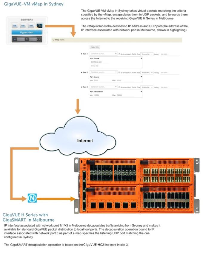
Configure Sending End of Tunnel: GigaVUE-VM vMap in Sydney
A GigaVUE-VM node in this location is configured with a vMap that will send data over the Internet to the IP interface associated with a network port on a GigaVUE H Series with a GigaSMART-HD0 line card installed.
VMaps are created in the GigaVUE-FM user interface – Step 2 in the Create Map wizard includes Tunnel Traffic To settings that specify where matching traffic should be sent:
|
Create vMap
“Tunnel Traffic To” Option
|
Setting
|
|
UDP IP
|
This is the destination IP address for the IP interface associated with network port on the GigaVUE H Series in Melbourne. We will set it to 10.150.68.222
|
|
UDP Source Port
|
This is the UDP source port from which tunneled packets will be sent. We will set this to 5000.
|
|
UDP Destination Port
|
This is the listening port on the receiving GigaVUE H Series IP interface associated with network port. We will set this to 10000.
|
Configure Receiving End of Tunnel:
GigaVUE H Series with GigaSMART in Melbourne
Now we need to configure the receiving end of the tunnel with an IP interface associated with network port. The GigaVUE H Series in this location will have an IP interface associated with network port configured on network port 1/1/3 with an IP address of 10.150.68.222 and a GigaSMART decapsulation operation that listens on UDP port 10000.
The following table summarizes the steps necessary to configure the receiving end of the tunnel using the UI:
|
Task
|
UI Steps
|
|
Start by designating port 1/1/x3 as an IP interface with network port, configuring its IP profile, and assigning its GigaSMART operations to a GigaSMART group. This command sets the IP address, subnet mask, default gateway, and MTU for the IP interface associated with a tool port on port 1/1/x3.
|
|
1.
|
Select Ports > IP Interfaces. |
|
3.
|
Configure the IP Interface: |
|
•
|
IP Address: 10.150.68.222 |
|
•
|
IP Mask: 255.255.255.255 |
|
|
Now, create an IP decapsulation GigaSMART operation (gmipdecap) that will decapsulate traffic received on UDP port 10000. Recall that we configured the sending end of the tunnel to send to that UDP port. The operation has the alias gv_ipdecap.
Note that this operation uses the same GigaSMART group (GS2) as the IP interface associated with network port we set up in the first step.
|
|
1.
|
From the device view, select GigaSMART > GigaSMART Operations > GigaSMART Operation. |
|
3.
|
Configure the GigaSMART Operation: |
|
•
|
GigaSMART Operations (GSOP): Tunnel Decapsulation |
|
4.
|
Configure the Tunnel Encapsulation: |
|
|
Once we have our IP decapsulation operation, we can include it as part of a map.
|
•
|
Open the map configuration page to create a map named decapper. |
|
•
|
The Source field specifies the ingress ports for this map. |
|
•
|
The GSOP field applies the gv_ipdecap GigaSMART operation to all packets matching the rules in the map, decapsulating them from the tunnel. |
|
•
|
The Destination field specifies where matching packets will be sent (tool port 1/1/x11). |
|
•
|
The rule with Pass selected specifies that packets arriving on this port with an IP Source address of 10.10.10.10 /32 will be processed by the gv_ipdecap GSOP and sent to tool port 1/1/x11. |
|
|
1.
|
Select Maps > Maps > Maps |
|
•
|
GigaSMART Operation (GSOP): gv_ipdecap (GS2) |
|
•
|
Select IPv4 Source for Rule 1. |
|
•
|
Set the IPv4 Address to 10.10.10.10 |
|
•
|
Set the Net Mask to 255.255.255.255 |
|


