GigaSMART Adaptive Packet Filtering (APF)
Required License: Adaptive Packet Filtering
Adaptive Packet Filtering (APF) provides filtering on specific encapsulation protocol parameters. Additionally, it has the ability to look beyond the encapsulation protocol parameters into the original (encapsulated) data packet, to filter on source and destination IP or Layer 4 port numbers. APF offers the ability to look for content anywhere in the data packet and make intelligent filtering and forwarding decisions.
Adaptive Packet Filtering includes fragmentation awareness whereby all IP fragments associated with the filtered data packet are always forwarded allowing a complete view of the traffic stream for accurate analytics. APF also provides a powerful filtering engine that identifies content (based on patterns) across any part of the data packet, including the data packet payload.
APF filters packet-by-packet, but does not have the concept of sessions. For Application Session Filtering (ASF) and packet buffering on ASF, refer to Application Session Filtering with Buffering.
APF operations can be assigned to GigaSMART groups consisting of multiple engine ports. Refer to Groups of GigaSMART Engine Ports for details.
In APF second level maps, a maximum of five (5) maps can be attached to a virtual port (vport). Each map can contain up to 25 gsrules.
Adaptive Packet Filtering (APF) goes deeper into packets to search for a condition, then filter and forward packets to tools, as follows:
Implement APF Through the UI
To create vports through the UI and implement APF, do the following:
- On the top navigation bar, click Physical, and then select the required cluster or node ID.
- From the left navigation pane, go to Traffic > GigaSMART > GigaSMART Groups > GigaSMART Groups, and then click New.
- On the GigaSMART Group page, select an available engine ports in the Port List field to associate group with one of the available engine ports.
You can associate the GigaSMART Group with one or multiple eports. For APF, no GigaSMART parameters are required unless combined with other gsops.
- From the device view, select GigaSMART > Virtual Ports, and then click New.
- On the Virtual Ports page, enter an alias and select the GigaSMART groups created in Step1, and then click Save.
- To enable the APF operation, do the following:
- From the device view, select GigaSMART > GigaSMART Operations (GSOP) > GigaSMART Operation.
- On the GigaSMART Operations page, enter an alias in the Alias field
- In the GigaSMART Groups drop-down list, select the GigaSMART group from step 1.
- From the GigaSMART Operations (GSOP) list, select Adaptive Packet Filtering and select Enabled.
- Click Save.
Once APF is enabled, maps can be created that the APF and the virtual port.
- Create the first level map with virtual port created in step 2 as the destination and without applying a GigaSMART Operation.
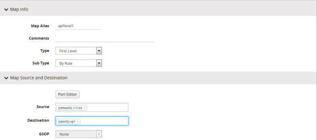
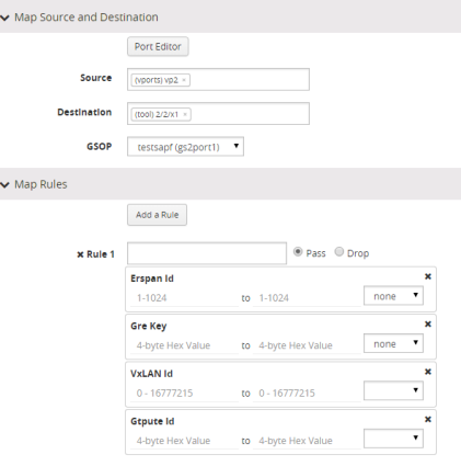
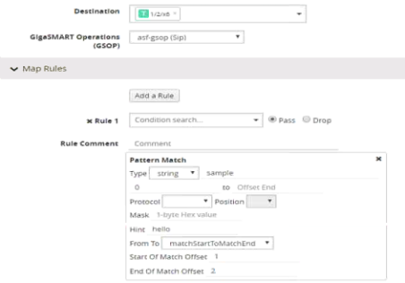
- Create a second level map with the APF GigaSMART operation, the virtual port as the source, and a rule. The following figure shows an example.
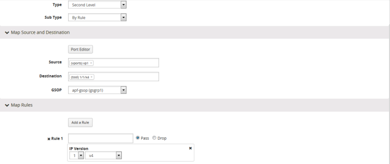
This completes the process to create an APF GigaSMART operation and corresponding rules. To learn more about the rules applicable for APF, see following sections.
Content-based Filtering
Content-based filtering is based on packet contents beyond Layer 2, 3, and 4 headers. The following four groups of attributes of rules in a map support content-based filtering.
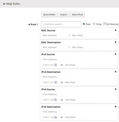
The first group of attributes has the following format:
<attribute> <address> <cidr>|<mask>
The first group of attributes that use this format are as follows:
The following figure shows the attributes as displayed in the UI.
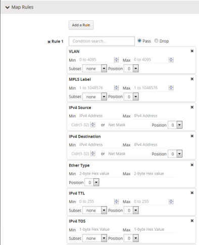
The second group of attributes has the following format:
<attribute> min <value> max <value> subset <odd|even|none> pos
The second group of attributes that use this format are as follows:
|
•
|
ipv4 ttl, tosval, and protocol |
|
•
|
vntag dvifid, svifid, and viflistid |
The following figure shows the attributes as displayed in the UI.
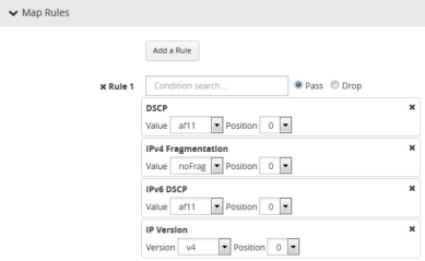
The third group of attributes has the following format: <value> <position>
<attribute> value <value> pos <0|1|..|n>
The third group of attributes that use this format are as follows:
The following figure show the attributes as displayed in the UI.
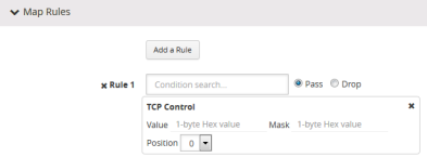
The fourth group of attributes has the following format:
<attribute> value <value> mask <mask> pos <0|1|2|3>
The fourth group of attribute that uses this format is as follows:
The following figure shows the attribute as displayed in the UI.
The maximum occurrences of each attribute supported are as follows:
|
Attribute
|
Maximum Occurrences
|
|
Attributes in IPv4 header
|
3
|
|
Attributes in IPv6 header
|
3
|
|
Attributes in MAC header
|
3
|
|
VLAN ID
|
4
|
|
MPLS label
|
4
|
|
Attributes in L4port
|
3
|
|
Ethertype
|
6
|
|
Attributes in VNTag header
|
3
|
|
Attributes in TCP header
|
3
|
|
IP ver
|
3
|
Encapsulation Awareness
Encapsulation awareness offers filtering across advanced encapsulation headers, including GTP tunnel ID, VXLAN ID, ERSPAN ID, and GRE key.
The following attributes of rules in a map support encapsulation awareness:
|
1.
|
Enter a GTP tunnel identifier as a four-byte hex value, either a range or a single value. |
|
2.
|
Enter a VXLAN ID as a three-byte hex value, either a range or a single value. |
|
3.
|
Enter an ERSPAN ID as a decimal value from 1~1024, either a range or a single value using the corresponding arguments. |
|
4.
|
Enter a GRE key as a four-byte hex value, either a range or a single value. |
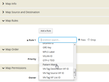
Pattern Matching
Use APF to create pattern matching filters in which the pattern is a particular sequence of data bytes at a variable or fixed offset from the start of a packet. Thus you can filter on any data patterns within a packet.
Pattern matching identifies content based on patterns in any part of the packet, including the payload. Patterns can be a static string at a user configured offset or a subset of Perl Compatible Regular Expression (PCRE) at a variable offset.
The Pattern Match attribute in a map rule supports pattern matching.
Multiple pattern matches are supported. A map can have multiple gsrules, each rule can have a pattern matching expression, and a single packet can match multiple rules.
The Pattern Match attribute in a map rule is shown in Figure 1: Use Pattern Match Under Maps for Pattern Matching.
|
Figure 25
|
Use Pattern Match Under Maps for Pattern Matching |
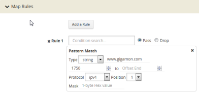
After selecting pattern matching for the rule, you can enter a Perl-compatible regular expression or a string to be used as a filter when pattern matching. For example to pass all packets including the string www.gigamon.com select string as type for the pattern match as shown in Figure 2: Pattern Match with Type String.
|
Figure 26
|
Pattern Match with Type String |
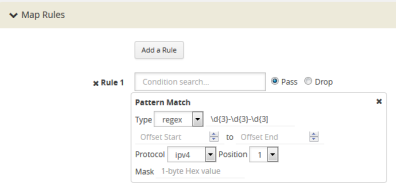
To pass packets that match any phone number in the nnn-nnn-nnnn format, select regex for the pattern match type and enter the following regular expression in the value field: \d{3}-d{3}-d{3} as shown in Figure 3: Pattern Match with Type RegEx.
|
Figure 27
|
Pattern Match with Type RegEx |
The offset is a value or range from 0 to 1750. The offset indicates where the pattern under search is located, specify, a value to indicate that the pattern has to start at that offset in the packet in order to be considered a match. Specify a range (beginning and ending) to indicate that the pattern can be anywhere in the packet in that range.
The optional protocol argument of the Pattern Match specifies that the matching will start after the protocol header specified in the command (IPv4, IPv6, TCP, or UDP). Pos 1 or 2 indicates the position. For example, position 2 indicates that matching is to start after the second protocol header. The offset and start and end values are also counted after the protocol header.
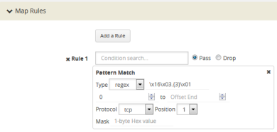
For example, to mask an SSL client hello packet pattern starting from the first position after the TCP header with an offset of 0 (located right after the TCP header), you define the pattern match rule as shown in Figure 4: Pattern Match for SSL Client Hello Packet.
|
Figure 28
|
Pattern Match for SSL Client Hello Packet |
Masking with Pattern Matching
APF allows masking when there is a match through pattern matching. Use masking with pattern matching to mask out a specific portion of a packet due to security reasons or to hide sensitive information in packets.
Multiple pattern matches are supported in a map. If there is masking associated with a rule and a packet matches multiple rules, the masking action is enforced for all the matching rules in the map.
The mask specifies that the matched pattern in the gsrule will be masked with the pattern specified in the 1-byte masking pattern.
The pattern specified in the gsrule will be overwritten. The overwritten length is the length of the matching pattern specified in either a string or a RegEx pmatch. Use the 1-byte to overwrite the original pattern match pattern. If there are multiple matches in the packet, up to 10 matches will be masked.
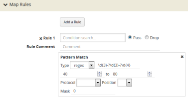
For example, to find Social Security numbers in the format xxx-xx-xxxx, between offset 40 and 80 and replace them with zeros, create a map with a pass rule in a Second Level byRule map with the regular expression \d{3}-?\d{2}-?{4} and a mask with a 1-byte masking value of 0 as shown in Figure 5: Map Rule with RegEx for Masking SSNs.
|
Figure 29
|
Map Rule with RegEx for Masking SSNs |
Pattern Matching Hint
To optimize APF pattern matching performance in second level maps with gsrules, you can optionally use a pattern matching hint. Refer to the example in Figure 6: Pattern Match with Hint.
|
Figure 30
|
Pattern Match with Hint |
The addition of the hint leads to two levels of filtering. First, the packet is subjected to a check for the simpler match comprising “gamon|GIM”. If a match is found, a second level check for a match in the complete RegEx, “a[gG]igamon|aGIMO\\s[a-f]\\d{4}”, is performed.
A hint must be selected so that all the packets that are expected to match the actual RegEx must have that string in them, otherwise the first level check will not be cleared. The hint in the example, “gamon|GIM”, was selected because a packet containing either “gamon” or “GIM” in it is a potential match to the actual RegEx.
Best Practices of Pattern Matching Hint
The pattern matching hint is optional and, to optimize performance, it should be specified for all gsrules in a map. In that map, its usage is all or none, meaning you cannot have a mix of gsrules with some having the pattern matching hint and others not. However, if there are two maps, one map can have gsrules that include the pattern matching hint, while the other map can have gsrules that do not.
The use of the pattern matching hint improves performance in complex RegEx patterns involving “lookbehind” and “lookahead” constructs of PCRE syntax. Using them in conjunction with maps with simple patterns, such as fixed length string, is not advisable as it might lead to performance degradation in some cases. Since the RegEx rule set is limitless, there are no specific rules in which the degradation happens. A best practice is to try out both options, with and without the pattern matching hint, to find out what works best.
The rule of thumb while constructing the pattern matching hint is to keep it as simple as possible. Also, it must be a subset of the configured RegEx pattern. First, try out a 3 to 6 character-wide hint. If that does not provide the necessary scale, you can make the hint wider and more specific to prevent false positives. A maximum length of 63 bytes is supported.
Cross-Packet Pattern Matching
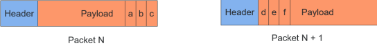
Cross-packet pattern matching refers to a scenario where a match initiates in one packet and ends in a subsequent packet. Staring with Gigamon software release 5.4 this feature enhancement extends the support for GSOP cross packet pattern spanning two packets.
Cross packet matching applies to connection oriented exchanges only and available for 5-tuple flows. Cross packet matching scan will be performed on frames with the following header encapsulations:
|
•
|
IPv4/IPv6/TCP, IPv4/IPV6/UDP |
|
•
|
IPV6/IPv4/TCP, IPV6/IPv4/UDC |
Every packet of a flow is subjected to pattern matching scan starting with the inner most L4 payload section. For example, 5-tuple TCP session with nested TCP layer will position the scan starting from start of innermost TCP payload to the end of frame. Bi-directional flow maintains match context for each direction separately and this feature supports up to 1Million flows.
The figure below illustrates the Cross-packet pattern matching concept where the pattern search “abcdef” spans two packets.
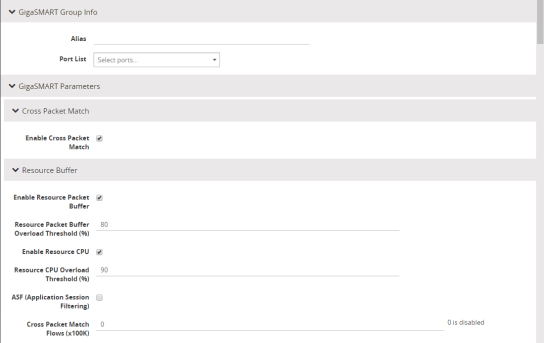
Enable/Disable Cross-packet Matching
You can enable or disable Cross-packet pattern matching from the GigaSMART GSOP operation.
|
1.
|
Select a Physical Node. |
|
2.
|
GigaSMART > GigaSMART > GigaSMART Groups. |
|
3.
|
Click New. The GigaSMART Group parameter page displays. |
|
4.
|
Click the Enable Cross-packet Match check box to enable. |
|
5.
|
Enter a range from 1 to 10 for the Cross Packet Match Flows parameter. Each unit is 100K bi-directional flows. |
Note: When disabling this functionality you will be notified that change will be effective only after chassis or GigaSMART card reboot.
Disable Cross Packet Matching
|
1.
|
Repeat Steps 1 through 3 from the “Enabling Cross Packet Matching” task. |
|
2.
|
Uncheck the Enable Cross-packet Match check box to disable this functionality. |
View Cross-packet Matching
|
1.
|
Select a Physical Node. |
|
2.
|
GigaSMART > GigaSMART > GigaSMART Groups. |
|
4.
|
Click Edit. The GigaSMART Group parameters including cross pattern match details pane displays. |
Limitations
The following constraints exist with this functionality.
|
•
|
Cannot coexist with other GSOPs on same gsgroup. |
|
•
|
Only one second level map is allowed for each vport attached to the gsgroup. |
|
•
|
Disabling the feature requires a GigaSMART card reboot. |
Map Statistics
Go to Map > Statistics to display counts of the rules that actually matched in a map. A single packet can match one or more rules. For example, if a single packet matches multiple rules in an APF map, all matching rules will have that packet counted against them and the overall map status pass counter will show 1.
APF Examples
The following are APF examples:
Identify Social Security Numbers in User-Level Transactions
The following example looks for packets containing Social Security Numbers in an incoming traffic stream using pattern matching. Once a match is detected, the packets are forwarded to a monitoring tool for additional analysis.
|
Task
|
Description
|
UI Steps
|
|
1
|
Configure one network and two tool ports.
|
|
1.
|
Select Ports > Ports > All Ports. |
|
2.
|
Click Quick Port Editor. |
|
3.
|
Configure one network port and two tool ports. For example, select Network for port 1/1/x3. Select Tool for port 1/1/x4 and port 1/1/x1. |
|
4.
|
Select Enable for each port. |
|
6.
|
Close the Quick Port Editor. |
|
|
2
|
Configure a GigaSMART group and associate it with a GigaSMART engine port.
|
|
1.
|
From the device view, select GigaSMART > GigaSMART Groups > GigaSMART Groups. |
|
3.
|
Type gsgrp1 in the Alias field. |
|
|
3
|
Configure the GigaSMART operation.
|
|
1.
|
From the device view, select GigaSMART > GigaSMART Operations (GSOP) > GigaSMART Operation. |
|
3.
|
Type gsfil in the Alias field. |
|
4.
|
Select gsgrp1 from the GigaSMART Groups list. |
|
5.
|
Select APF from the GigaSMART Operations (GSOP) list. |
|
|
4
|
Create a virtual port.
|
|
1.
|
From the device view, select GigaSMART > Virtual ports. |
|
3.
|
Enter vp1 in the Alias field. |
|
4.
|
Select gsgrp1 from the GigaSMART Groups list. |
|
|
5
|
Create a first level map to forward traffic from network port 1/1/x3 to virtual port vp1.
|
|
1.
|
Select Maps > Maps > Maps. |
|
•
|
Enter map1 in the Alias field. |
|
•
|
Select First Level for Type. |
|
•
|
Select By Rule for Subtype. |
|
•
|
Select the port 1/1/x3 for the Source. |
|
•
|
Select the virtual port vp1 for the Destination. |
|
d.
|
Select v4 for Version. |
|
|
6
|
Create a second level map to forward traffic from the virtual port vp1 to GigaSMART with pattern matching.
|
|
1.
|
Select Maps > Maps > Maps. |
|
•
|
Enter map2 in the Alias field. |
|
•
|
Select Second Level for Type. |
|
•
|
Select By Rule for Subtype. |
|
•
|
Select the virtual port vp1 for the Source. |
|
•
|
Select the tool port 1/1/x1 for the Destination. |
|
c.
|
Select Pattern Matching. |
|
d.
|
Select regex for Type and enter the value d{3}-?\d{2}-?\d{4}. |
|
e.
|
Set the Offset Start to 40. |
|
f.
|
Set the Offset End to 80 |
|
Mask Social Security Numbers
In the following pattern matching example, IPv4 packets contain Social Security Numbers (SSNs) in the format xxx-xx-xxxx. If the SSNs are between offset 40 and 80, they will be replaced with zeros.
|
Task
|
Description
|
UI Steps
|
|
1
|
Configure a GigaSMART group and associate it with a GigaSMART engine port.
|
|
1.
|
From the device view, select GigaSMART > GigaSMART Groups > GigaSMART Groups. |
|
3.
|
Type gsgrp1 in the Alias field. |
|
|
2
|
Create a virtual port and associate it with the GigaSMART group.
|
|
1.
|
From the device view, select GigaSMART > Virtual ports. |
|
3.
|
Enter gsTraffic in the Alias field. |
|
4.
|
Select gsgrp1 from the GigaSMART Groups list. |
|
|
3
|
Create a first level map to direct traffic from network port 1/1/x1 to virtual port gsTraffic.
|
|
1.
|
Select Maps > Maps > Maps. |
|
•
|
Enter map1 in the Alias field. |
|
•
|
Select First Level for Type. |
|
•
|
Select By Rule for Subtype. |
|
•
|
Select the port 1/1/x3 for the Source. |
|
•
|
Select the virtual port gsTraffic for the Destination. |
|
d.
|
Select v4 for Version. |
|
|
4
|
Configure the GigaSMART operation.
|
|
1.
|
From the device view, select GigaSMART > GigaSMART Operations (GSOP) > GigaSMART Operations. |
|
3.
|
Select gsgrp1 from the GigaSMART Groups list. |
|
4.
|
Select Adaptive Packet Filtering from the GigaSMART Operations (GSOP) list. |
|
|
5
|
Create a second level map to direct traffic from the virtual port gsTraffic to GigaSMART.
|
|
1.
|
Select Maps > Maps > Maps. |
|
•
|
Enter map2 in the Alias field. |
|
•
|
Select Second Level for Type. |
|
•
|
Select By Rule for Subtype. |
|
•
|
Select the virtual port vp1 for the Source. |
|
•
|
Select the tool port 1/1/x6 for the Destination. |
|
•
|
Select gsop1 from the GSOP list. |
|
c.
|
Select Pattern Matching. |
|
d.
|
Select regex for Type and enter the value d{3}-?\d{2}-?\d{4}. |
|
e.
|
Set the Offset Start to 40. |
|
f.
|
Set the Offset End to 80 |
|
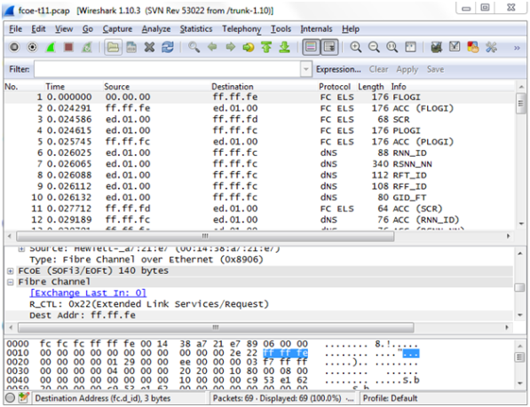
Filter on Fiber Channel over Ethernet (FCOE) Traffic
The flexibility offered by regular expression-based filters can be used as an infrastructure to classify traffic streams with protocol headers that are typically unsupported on traditional TAP/SPAN aggregation devices. In this example, regular expression-based filters are used for filtering on the source address in a Fiber Channel header.
|
Task
|
Description
|
UI Steps
|
|
1
|
Configure ports.
|
|
1.
|
Select Ports > Ports > All Ports. |
|
2.
|
Click Quick Port Editor. |
|
3.
|
Configure one network port and two tool ports. For example, select Network for port 1/1/x3. Select Tool for port 1/1/x4 and port 1/1/x1. |
|
4.
|
Select Enable for each port. |
|
6.
|
Close the Quick Port Editor. |
|
|
2
|
Configure a GigaSMART group and associate it with a GigaSMART engine port.
|
|
1.
|
From the device view, select GigaSMART > GigaSMART Groups > GigaSMART Groups. |
|
3.
|
Type gsgrp1 in the Alias field. |
|
|
3
|
Configure the GigaSMART operation.
|
|
1.
|
From the device view, select GigaSMART > GigaSMART Operations (GSOP) > GigaSMART Operation. |
|
3.
|
Select gsfil from the GigaSMART Groups list. |
|
4.
|
Select Adaptive Packet Filtering from the GigaSMART Operations list. |
|
|
4
|
Create a virtual port and associate it with the GigaSMART group.
|
|
1.
|
From the device view, select GigaSMART > Virtual ports. |
|
3.
|
Enter gsTraffic in the Alias field. |
|
4.
|
Select gsgrp1 from the GigaSMART Groups list. |
|
|
5
|
Create a first level map to forward FCOE traffic to the virtual port.
|
|
1.
|
Select Maps > Maps > Maps. |
|
•
|
Enter to_vp in the Alias field. |
|
•
|
Select First Level for Type. |
|
•
|
Select By Rule for Subtype. |
|
•
|
Select the port 1/1/x3 for the Source. |
|
•
|
Select the virtual port vp1 for the Destination. |
|
d.
|
Enter 8906 in the Value field. |
|
|
6
|
Create a second level map to filter on regular expression, using a string match to the destination address in the FCOE packet.
|
|
1.
|
Select Maps > Maps > Maps. |
|
•
|
Enter map2 in the Alias field. |
|
•
|
Select Second Level for Type. |
|
•
|
Select By Rule for Subtype. |
|
•
|
Select the virtual port vp1 for the Source. |
|
•
|
Select the tool port 1/1/x1 for the Destination. |
|
•
|
Select gsfil from the GSOP list. |
|
d.
|
Select string for Type and enter txff\xff\xfe. |
|
e.
|
Set the Offset Start to 0. |
|
f.
|
Set the Offset End to 29 |
|
Multi-Encapsulation Filtering
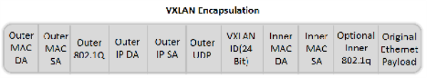
In order to complement the mobility brought about by the virtualized server infrastructure, network virtualization overlays like VXLAN, VNTag, NVGRE are being designed and implemented in Data Centers and Enterprise environment. Across Service Provider environments, huge volumes of traffic are being tunneled over GTP. Until now, the GigaVUE Visibility Platform provided the option of stripping out these headers, thus providing visibility to monitoring tools that do not understand these overlays and encapsulation protocol. With APF, this capability is further enhanced where operators now have the option of making forwarding decisions based on the encapsulation and inner packet contents.
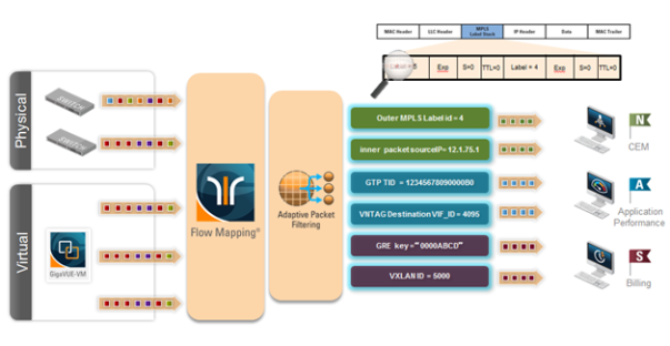
With encapsulation awareness enabled by APF, operators have multiple options to act on the packet including the flexibility to:
|
•
|
Filter on encapsulation header parameters, Layer 2 – 4 parameters in the outer or inner headers (up to 5 layers of encapsulation) in any combination. For example: |
|
•
|
Forward traffic specific to a subset of VXLAN IDs to one or more monitoring tools. |
|
•
|
Distribute traffic based on MPLS label values across one or more monitoring tools. |
|
•
|
In combination with header stripping: |
|
•
|
Implement “conditional” header-stripping, based on encapsulation header parameters or inner/outer packet contents, as follows: |
– Forward a subset of traffic “as-is” to monitoring tools that need these encapsulations for analysis.
– Alternatively, strip out the outer headers/encapsulations and distribute traffic to monitoring tools that do not require these outer headers for analysis.
|
•
|
Since APF is implemented as a second level map, operators can also implement overlapping rules where: |
|
•
|
A copy of the traffic can be distributed across a group of monitoring tools. |
|
•
|
A refined subset from the same incoming stream is distributed across a different set of tools. |
Filter on Subscriber Device IP (User-Endpoint IP or UE-IP)
Encapsulation awareness enabled by APF allows mobile operators to filter on Layer 2 – 4 header parameters found in an encapsulated packet.
This allows operators to filter and forward traffic specific to a mobile subscriber device or a group of subscriber devices, identified by their IP address (User-Endpoint IP) to one or more monitoring tools.
In this example, we are:
|
•
|
Identifying and forwarding traffic from / to a UE-IP of 1.1.1.1 to a monitoring tool connected to 1/1/x1 |
|
•
|
Identifying and forwarding traffic from / to a UE-IP of 1.1.1.2 to a different monitoring tool connected to tool port 1/1/x4 |
In many cases, the GTP control sessions are low-volume and are useful in providing some level of visibility in to the quality of experience of the subscribers. To this end, operators prefer to replicate the control sessions across all the monitoring tools, while filtering and forwarding a subset of the user-plane sessions to a subset of monitoring tools. The following example also illustrates configuration commands, leveraging the patented flow-mapping technology to replicate the GTP control sessions across all the monitoring tools involved in the traffic analysis.
|
Task
|
Description
|
UI Steps
|
|
1
|
Configure ports.
|
|
1.
|
Select Ports > Ports > All Ports. |
|
2.
|
Click Quick Port Editor. |
|
3.
|
Configure one network port and two tool ports. For example, select Network for port 1/1/x3. Select Tool for port 1/1/x4 and port 1/1/x1. |
|
4.
|
Select Enable for each port. |
|
6.
|
Close the Quick Port Editor. |
|
|
2
|
Configure a GigaSMART group and associate it with a GigaSMART engine port.
|
|
1.
|
From the device view, select GigaSMART > GigaSMART Groups > GigaSMART Groups. |
|
3.
|
Type gsg1 in the Alias field. |
|
4.
|
Select engine port 1/1/e1 in the Port List field. |
|
|
3
|
Configure the GigaSMART operation.
|
|
1.
|
From the device view, select GigaSMART > GigaSMART Operations (GSOP) > GigaSMART Operations. |
|
3.
|
Type gsfil in the Alias field. |
|
4.
|
Select gsg1 from the GigaSMART Groups list. |
|
5.
|
Select Adaptive Packet Filtering from the GigaSMART Operations (GSOP) list. |
|
|
4
|
Create a virtual port and associate it with the GigaSMART group.
|
|
1.
|
From the device view, select GigaSMART > Virtual ports. |
|
3.
|
Enter vp1 in the Alias field. |
|
4.
|
Select gsgrp1 from the GigaSMART Groups list. |
|
|
5
|
Create a first level map to forward GTP-u traffic to the virtual port.
Note: In the rule, 2152 is GTP-u traffic.
|
|
1.
|
Select Maps > Maps > Maps. |
|
•
|
Enter to_vp in the Alias field. |
|
•
|
Select First Level for Type. |
|
•
|
Select By Rule for Subtype. |
|
•
|
Select the port 1/1/x3 for the Source. |
|
•
|
Select the virtual port vp1 for the Destination. |
|
d.
|
Enter 2152 for the port value. |
|
|
6
|
Create a first level map to forward GTP-c traffic to the tools.
Note: In the rule, 2123 is GTP-c traffic.
|
|
1.
|
Select Maps > Maps > Maps. |
|
•
|
Type to_tool in the Alias field. |
|
•
|
Select Regular for Type. |
|
•
|
Select By Rule for Subtype. |
|
•
|
Select the port 1/1/x3 for the Source. |
|
•
|
Select port 1/1/x1 and port 1/1/x4 for the Destination. |
|
d.
|
Enter 2123 for the port value. |
|
|
7
|
Create a second level map to filter on source and destination IP (bi-directional).
|
|
1.
|
Select Maps > Maps > Maps. |
|
•
|
Enter map1 in the Alias field. |
|
•
|
Select Second Level for Type. |
|
•
|
Select By Rule for Subtype. |
|
•
|
Select the virtual port vp1 for the Source. |
|
•
|
Select the tool port 1/1/x1 for the Destination. |
|
•
|
Select gsfil from the GSOP list. |
|
d.
|
Enter 1.1.1.1 for the IPv4 Address |
|
e.
|
Enter 255.255.255.255 for the Net Mask |
|
c.
|
Select IPv4 Destination. |
|
d.
|
Enter 1.1.1.1 for the IPv4 Address |
|
e.
|
Enter 255.255.255.255 for the Net Mask |
|
|
8
|
Create another second level map to filter on source and destination IP (bi-directional).
|
|
1.
|
Select Maps > Maps > Maps. |
|
•
|
Enter map1 in the Alias field. |
|
•
|
Select Second Level for Type. |
|
•
|
Select By Rule for Subtype. |
|
•
|
Select the virtual port vp1 for the Source. |
|
•
|
Select the tool port 1/1/x4 for the Destination. |
|
•
|
Select gsfil from the GSOP list. |
|
d.
|
Enter 1.1.1.1 for the IPv4 Address |
|
e.
|
Enter 255.255.255.255 for the Net Mask |
|
c.
|
Select IPv4 Destination. |
|
d.
|
Enter 1.1.1.1 for the IPv4 Address |
|
e.
|
Enter 255.255.255.255 for the Net Mask |
|
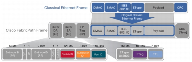
Filter on Inner Layer 2-4 Parameters for Unrecognized Headers
The flexibility of encapsulation awareness enables filtering on encapsulated contents even if APF does not recognize the outer encapsulation header. The following example illustrates a packet encapsulated in Fabric Path headers. Fabric Path headers (as shown in the figure) are mac-in-mac headers that are currently not recognized by APF. However operators can still filter and forward traffic flows based on Layer 2 – 4 parameters found in the encapsulated packets.
In this example, we are:
|
•
|
Identifying and forwarding traffic from/to ip 1.1.1.1 in the inner / original packet to monitoring tool connected to tool port 1/1/x1 |
|
•
|
Identifying and forwarding traffic from/to ip 1.1.1.2 in the inner / original packet to monitoring tool connected to tool port 1/1/x4 |
|
Task
|
Description
|
UI Steps
|
|
1
|
Configure ports.
|
|
1.
|
Select Ports > Ports > All Ports. |
|
2.
|
Click Quick Port Editor. |
|
3.
|
Configure one network port and two tool ports. For example, select Network for port 1/1/x3. Select Tool for port 1/1/x4 and port 1/1/x1. |
|
4.
|
Select Enable for each port. |
|
6.
|
Close the Quick Port Editor. |
|
|
2
|
Configure a GigaSMART group and associate it with a GigaSMART engine port.
|
|
1.
|
From the device view, select GigaSMART > GigaSMART Groups > GigaSMART Groups. |
|
3.
|
Type gsg1 in the Alias field. |
|
4.
|
Select engine port 1/1/e1 in the Port List field. |
|
|
3
|
Configure the GigaSMART operation.
|
|
1.
|
From the device view, select GigaSMART > GigaSMART Operations (GSOP) > GigaSMART Operation. |
|
4.
|
Select gsfil from the GigaSMART Groups list. |
|
5.
|
Select Adaptive Packet Filtering from the GigaSMART Operations (GSOP) list. |
|
|
4
|
Create a virtual port and associate it with the GigaSMART group.
|
|
1.
|
From the device view, select GigaSMART > Virtual ports. |
|
3.
|
Enter vp1 in the Alias field. |
|
4.
|
Select gsgrp1 from the GigaSMART Groups list. |
|
|
5
|
Create a first level map to forward fabric path packets to the virtual port.
|
|
1.
|
Select Maps > Maps > Maps. |
|
•
|
Enter to_vp in the Alias field. |
|
•
|
Select First Level for Type. |
|
•
|
Select By Rule for Subtype. |
|
•
|
Select the port 1/1/x3 for the Source. |
|
•
|
Select the virtual port vp1 for the Destination. |
|
d.
|
Enter 8903 in the Value field. |
|
|
6
|
Create a second level map to filter on source and destination IP (bi-directional).
|
|
1.
|
Select Maps > Maps > Maps. |
|
•
|
Enter map1 in the Alias field. |
|
•
|
Select Second Level for Type. |
|
•
|
Select By Rule for Subtype. |
|
•
|
Select the virtual port vp1 for the Source. |
|
•
|
Select the tool port 1/1/x1 for the Destination. |
|
•
|
Select gsfil from the GSOP list. |
|
d.
|
Enter 1.1.1.1 for the IPv4 Address |
|
e.
|
Enter 255.255.255.255 for the Net Mask |
|
c.
|
Select IPv4 Destination. |
|
d.
|
Enter 1.1.1.1 for the IPv4 Address |
|
e.
|
Enter 255.255.255.255 for the Net Mask |
|
|
7
|
Create another second level map to filter on source and destination IP (bi-directional).
|
|
1.
|
Select Maps > Maps > Maps. |
|
•
|
Enter map1 in the Alias field. |
|
•
|
Select Second Level for Type. |
|
•
|
Select By Rule for Subtype. |
|
•
|
Select the virtual port vp1 for the Source. |
|
•
|
Select the tool port 1/1/x4 for the Destination. |
|
•
|
Select gsfil from the GSOP list. |
|
d.
|
Enter 1.1.1.2 for the IPv4 Address |
|
e.
|
Enter 255.255.255.255 for the Net Mask |
|
c.
|
Select IPv4 Destination. |
|
d.
|
Enter 1.1.1.2 for the IPv4 Address |
|
e.
|
Enter 255.255.255.255 for the Net Mask |
|
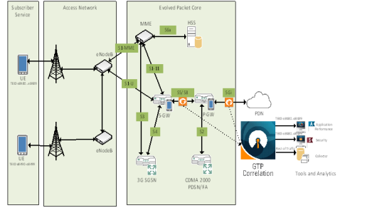
GTP Tunnel ID-Based Filtering
The following example demonstrates filtering and forwarding traffic based on tunnel IDs included as part of the GTP user-plane messages. It also illustrates the concept of a shared collector to which traffic not matching any of the configured filters can be optionally sent. GTP control sessions are forwarded to all the monitoring tools leveraging the power of flow mapping by filtering on Layer-4 UDP port 2123.
For GTP-u:
|
•
|
Filter and forward teid ranges 0x001e8480..0x001e8489 to a monitoring tool |
|
•
|
Filter and forward teid ranges 0x001e8490..0x001e8499 to another monitoring tool |
|
•
|
Forward the rest of the traffic to a shared collector |
|
Task
|
Description
|
UI Steps
|
|
1
|
Configure one network and three tool type of ports.
|
|
1.
|
Select Ports > Ports > All Ports. |
|
2.
|
Click Quick Port Editor. |
|
3.
|
Configure one network port and two tool ports. For example, select Network for port 1/1/x9. Select Tool for the port s 1/1/x13,
1/1/x14, and 1/1/x15. |
|
4.
|
Select Enable for each port. |
|
6.
|
Close the Quick Port Editor. |
|
|
2
|
Configure a GigaSMART group and associate it with a GigaSMART engine port.
|
|
1.
|
From the device view, select GigaSMART > GigaSMART Groups > GigaSMART Groups. |
|
3.
|
Type gsg1 in the Alias field. |
|
4.
|
Select engine port 1/1/e1 in the Port List field. |
|
|
3
|
Configure the GigaSMART operation and assign it to the GigaSMART group. Packets processed by this operation are evaluated using Adaptive Packet Filtering (APF) rules.
|
|
1.
|
From the device view, select GigaSMART > GigaSMART Operations (GSOP) > GigaSMART Operation. |
|
3.
|
Type gsfil in the Alias field. |
|
4.
|
Select gsg1 from the GigaSMART Groups list. |
|
5.
|
Select Adaptive Packet Filtering from the GigaSMART (GSOP) Operations list. |
|
|
4
|
Create a virtual port and associate it with the GigaSMART group.
|
|
1.
|
From the device view, select GigaSMART > Virtual ports. |
|
3.
|
Enter vp1 in the Alias field. |
|
4.
|
Select gsgrp1 from the GigaSMART Groups list. |
|
|
5
|
Create a first level map that directs GTP-u traffic from physical network port/s to the virtual port created in the previous step.
Note: In the rule, 2152 is GTP-u traffic.
|
|
1.
|
Select Maps > Maps > Maps. |
|
•
|
Enter to_vp in the Alias field. |
|
•
|
Select First Level for Type. |
|
•
|
Select By Rule for Subtype. |
|
•
|
Select the port 1/3/x9 for the Source. |
|
•
|
Select the virtual port vp1 for the Destination. |
|
d.
|
Enter 8903 in the Value field. |
|
|
6
|
Create a first level map that directs GTP-u traffic from physical network port/s to the tool ports.
Note: In the rule, 2123 is GTP-c traffic.
|
|
1.
|
Select Maps > Maps > Maps. |
|
•
|
Enter ctrl_to_tool in the Alias field. |
|
•
|
Select Regular for Type. |
|
•
|
Select By Rule for Subtype. |
|
•
|
Select the port 1/3/x9 for the Source. |
|
•
|
Select the port 1/3/x13 and port 1/3/x15 for the Destination. |
|
d.
|
Enter 2123 for the port value. |
|
|
7
|
Create a second level map that takes traffic from the virtual port, applies the GigaSMART operation, and matches tunnel IDs specified by the gsrule.
|
|
1.
|
Select Maps > Maps > Maps. |
|
•
|
Type m1 in the Alias field. |
|
•
|
Select Second Level for Type. |
|
•
|
Select By Rule for Subtype. |
|
•
|
Select the port 1/3/x15 for the Source. |
|
•
|
Select the virtual port vp1 for the Destination. |
|
•
|
Select gsfil from the GSOP list. |
|
d.
|
Enter 0x001e8480 for Min and 0x001e8489 for Max. |
|
|
8
|
Create a second level map that takes traffic from the virtual port, applies the GigaSMART operation, and matches tunnel IDs specified by the gsrule.
|
|
1.
|
Select Maps > Maps > Maps. |
|
•
|
Type m2 in the Alias field. |
|
•
|
Select Second Level for Type. |
|
•
|
Select By Rule for Subtype. |
|
•
|
Select the port 1/3/x15 for the Source. |
|
•
|
Select the virtual port vp1 for the Destination. |
|
•
|
Select gsfil from the GSOP list. |
|
d.
|
Enter 0x001e8490 for Min and 0x001e8499 for Max. |
|
|
9
|
Add a shared collector for any unmatched data and send it to the third tool port.
|
|
1.
|
Select Maps > Maps > Maps. |
|
•
|
Type scoll in the Alias field. |
|
•
|
Select Second Level for Type. |
|
•
|
Select Collector for Subtype. |
|
•
|
Select the virtual port vp1 for the Source. |
|
•
|
Select the port 1/3/x14 for the Destination. |
|
•
|
Select gsfil from the GSOP list. |
|
ERSPAN Tunneling
In this example, APF is used to filter packets based on ERSPAN ID. The ERSPAN header is not removed from the packet.
A second level map is configured in the example. A virtual port feeds traffic to the second level map. APF filters the packets and forwards those that match the filter criteria in the map.
|
Task
|
Description
|
UI Steps
|
|
1
|
Configure a tool type of port.
|
|
1.
|
Select Ports > Ports > All Ports. |
|
2.
|
Click Quick Port Editor. |
|
3.
|
Select Tool for a port. For example, port 1/1/g1. |
|
6.
|
Close the Quick Port Editor. |
|
|
2
|
Configure a GigaSMART group and associate it with a GigaSMART engine port.
|
|
1.
|
From the device view, select GigaSMART > GigaSMART Groups > GigaSMART Groups. |
|
3.
|
Type gsgp2 in the Alias field. |
|
4.
|
Select an engine port 1/3/e1 in the Port List field. For example,
1/3/e2 |
|
|
3
|
Create a virtual port and associate it with the GigaSMART group.
|
|
1.
|
From the device view, select GigaSMART > Virtual ports. |
|
3.
|
Enter vp in the Alias field. |
|
4.
|
Select gsgrp2 from the GigaSMART Groups list. |
|
|
4
|
Configure the GigaSMART operation and assign it to the GigaSMART group.
|
|
1.
|
From the device view, select GigaSMART > GigaSMART Operations (GSOP) > GigaSMART Operations. |
|
3.
|
Type er2 in the Alias field. |
|
4.
|
Select gsgp2 from the GigaSMART Groups list. |
|
5.
|
Select Adaptive Packet Filtering from the GigaSMART Operations list. |
|
|
5
|
Create a first level map.
|
|
1.
|
Select Maps > Maps > Maps. |
|
•
|
Type test1a in the Alias field. |
|
•
|
Select First Level for Type. |
|
•
|
Select By Rule for Subtype. |
|
•
|
Select the network port for the Source. For example, 1/1/g3. |
|
•
|
Select the virtual port vp for the Destination. |
|
•
|
Select gsfil from the GSOP list. |
|
d.
|
Enter the address 0000.0000.0000 for Min and the address 0000.0000.0000 for Max. |
|
|
6
|
Create a second level map.
|
|
1.
|
Select Maps > Maps > Maps. |
|
•
|
Type test1b in the Alias field. |
|
•
|
Select Second Level for Type. |
|
•
|
Select By Rule for Subtype. |
|
•
|
Select the network port for the Source. For example, 1/1/g3. |
|
•
|
Select the virtual port vp for the Destination. |
|
•
|
Select er2 from the GSOP list. |
|
d.
|
Enter the address 0000.0000.0000 for Min and the address 0000.0000.0000 for Max. |
|
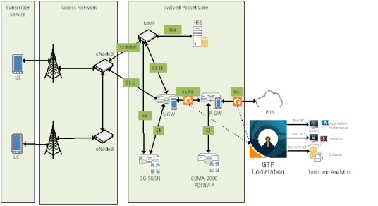
Distribute Traffic Based on Inner IP Addresses and Inner TCP Port Values
In the following example, traffic is distributed based on inner IP addresses and inner TCP port values as follows:
|
•
|
Packets from VLAN 20 with GTP inner IP 65.128.7.21 and 98.43.132.70, inner TCP port 80 is forwarded to one tool port |
|
•
|
Packets from VLAN 20 with GTP inner IP 65.128.7.21 and 98.43.132.70, inner TCP port 443 is forwarded to a second tool port |
|
•
|
All packets not matching these rules is forwarded to a third tool port |
|
Task
|
Description
|
UI Steps
|
|
1
|
Configure one network and three tool type of ports.
|
|
1.
|
Select Ports > Ports > All Ports. |
|
2.
|
Click Quick Port Editor. |
|
3.
|
Configure one network port and three tool ports. For example, select Network for port 1/1/x1. Select Tool for the port s 1/1/x10,
1/1/x11, and 1/1/x12. |
|
4.
|
Select Enable for each port. |
|
6.
|
Close the Quick Port Editor. |
|
|
2
|
Configure a GigaSMART group and associate it with a GigaSMART engine port.
|
|
1.
|
From the device view, select GigaSMART > GigaSMART Groups > GigaSMART Groups. |
|
3.
|
Type gsgrp1 in the Alias field. |
|
4.
|
Select an engine port in the Port List field. For example, 1/1/e1. |
|
|
3
|
Configure the GigaSMART operation and assign it to the GigaSMART group. Packets processed by this operation are evaluated using Adaptive Packet Filtering (APF) rules.
|
|
1.
|
From the device view, select GigaSMART > GigaSMART Operations (GSOP) > GigaSMART Operation. |
|
3.
|
Type g1 in the Alias field. |
|
4.
|
Select gsgrp1 from the GigaSMART Groups list. |
|
5.
|
Select APF from the GigaSMART Operations (GSOP) list. |
|
|
4
|
Configure a virtual port and associate it with the GigaSMART group.
|
|
1.
|
From the device view, select GigaSMART > Virtual ports. |
|
3.
|
Enter gsTraffic in the Alias field. |
|
4.
|
Select gsgrp1 from the GigaSMART Groups list. |
|
|
5
|
Create a first level map that directs traffic from the physical network port to the virtual port created in the previous step.
|
|
1.
|
Select Maps > Maps > Maps. |
|
•
|
Type map1 in the Alias field. |
|
•
|
Select First Level for Type. |
|
•
|
Select By Rule for Subtype. |
|
•
|
Select the network port for the Source. For example, 1/1/x1 |
|
•
|
Select the virtual port gsTraffic for the Destination. |
|
4.
|
Add a rule with three conditions. |
|
c.
|
Select VLAN and enter 20 for Min. |
|
d.
|
Select IPv4 Protocol and select UDP for Value. |
|
e.
|
Select Port Destination and enter 2152 for the port value |
|
|
6
|
Create a second level map that takes traffic from the virtual port, applies the GigaSMART operation, matches the rules, and sends the traffic to one tool port.
|
|
1.
|
Select Maps > Maps > Maps. |
|
•
|
Type map2 in the Alias field. |
|
•
|
Select Second Level for Type. |
|
•
|
Select By Rule for Subtype. |
|
•
|
Select the virtual port gsTraffic for the Source. |
|
•
|
Select the port 1/1/x10 for the Destination. |
|
•
|
Select g1 from the GSOP list. |
|
4.
|
Add a rule with three conditions. |
|
c.
|
Select IPv4 Destination then enter 65.128.721 for the IP address and 255.255.255.255 for the Net Mask. Set position to 2. |
|
d.
|
Select IPv4 Protocol and set the Potion to 2. |
|
e.
|
Select Port Destination and enter 80 for the port value and select 2 for Position. |
|
6.
|
Add a rule with three conditions. |
|
c.
|
Select IPv4 Destination then enter 98.43.132.70 for the IP address and 255.255.255.255 for the Net Mask. Set Position to 2. |
|
d.
|
Select IPv4 Protocol and set the Position to 2. |
|
e.
|
Select Port Destination and enter 80 for the port value and select 2 for Position. |
|
|
7
|
Create a second level map that takes traffic from the virtual port, applies the GigaSMART operation, matches the rules, and sends the traffic to another tool port.
|
|
1.
|
Select Maps > Maps > Maps. |
|
•
|
Type map3 in the Alias field. |
|
•
|
Select Second Level for Type. |
|
•
|
Select By Rule for Subtype. |
|
•
|
Select the virtual port gsTraffic for the Source. |
|
•
|
Select the port 1/1/x10 for the Destination. |
|
•
|
Select g1 from the GSOP list. |
|
4.
|
Add a rule with three rule conditions. |
|
c.
|
Select IPv4 Destination then enter 65.128.721 for the IP address and 255.255.255.255 for the Net Mask. Set Position to 2. |
|
d.
|
Select IPv4 Protocol. Set Position to 2 |
|
e.
|
Select Port Destination and enter 443 for the port value and select 2 for Position. |
|
6.
|
Add another rule with three rule conditions. |
|
c.
|
Select IPv4 Destination then enter 98.43.132.70 for the IP address and 255.255.255.255 for the Net Mask. Set position to 2. |
|
d.
|
Select IPv4 Protocol. Set position to 2. |
|
e.
|
Select Port Destination and enter 443 for the port value and set Position to 2. |
|
|
8
|
Add a shared collector for any unmatched data and send it to the third tool port.
|
|
1.
|
Select Maps > Maps > Maps. |
|
•
|
Type mapclin the Alias field. |
|
•
|
Select Second Level for Type. |
|
•
|
Select Collector for Subtype. |
|
•
|
Select the virtual port gsTraffic for the Source. |
|
•
|
Select the port 1/1/x12 for the Destination. |
|
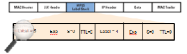
MPLS Label Based Filtering
Multiprotocol Label Switching (MPLS) is a mechanism in high-performance telecommunications networks that directs data from one network node to the next based on short path labels rather than long network addresses, avoiding complex lookups in a routing table. The labels identify virtual links (paths) between distant nodes rather than endpoints.
MPLS is a scalable, protocol-independent transport. In an MPLS network, data packets are assigned labels. Packet-forwarding decisions are made solely on the contents of this label, without the need to examine the packet itself. This allows one to create end-to-end circuits across any type of transport medium, using any protocol.
However in the context of Visibility Platform nodes, traffic flows encapsulated in MPLS labels cannot be filtered and forwarded. With the wide-scale adoption of MPLS as a technology across enterprise and service provider environments, the ability to classify traffic flows based on MPLS labels would be a huge value add to granularly control the flow of traffic to the monitoring tools. APF can be leveraged to filter and forward traffic flows based on MPLS label values. MPLS can stack multiple labels to form tunnels within tunnels. The flexibility of APF facilitates traffic classifications across up to 5 levels of MPLS label stacks in addition to the capability to filter and forward based on Layer 2-4 parameters found in the encapsulated packet. The following example illustrates filtering and forwarding traffic based on MPLS labels, as follows:
|
•
|
Filter and forward traffic flows specific to mpls label = 4 at the second level in the MPLS label stack to tool 1 |
|
•
|
Filter and forward traffic flows specific to mpls label = 3 at the first level in the MPLS label stack to tool 2 |
|
Step
|
Description
|
Command
|
|
1
|
Configure ports.
|
|
1.
|
Select Ports > Ports > All Ports. |
|
2.
|
Click Quick Port Editor. |
|
3.
|
Configure one network port and two tool ports. For example, select Network for port 1/1/x3 and select Tool for the port s 1/1/x4 and
1/1/x1 |
|
4.
|
Select Enable for each port. |
|
6.
|
Close the Quick Port Editor. |
|
|
2
|
Configure a GigaSMART group and associate it with a GigaSMART engine port.
|
|
1.
|
From the device view, select GigaSMART > GigaSMART Groups > GigaSMART Groups. |
|
3.
|
Type gsg1 in the Alias field. |
|
4.
|
Select an engine port in the Port List field. For example,
1/1/e1 |
|
|
3
|
Configure the GigaSMART operation.
|
|
1.
|
From the device view, select GigaSMART > GigaSMART Operations (GSOP) > Operations. |
|
3.
|
Type gsfil in the Alias field. |
|
4.
|
Select gsg1 from the GigaSMART Groups list. |
|
5.
|
Select APF from the GigaSMART Operations list. |
|
|
4
|
Create a virtual port and associate it with the GigaSMART group.
|
|
1.
|
From the device view, select GigaSMART > Virtual ports. |
|
3.
|
Enter vp1 in the Alias field. |
|
4.
|
Select gsg1 from the GigaSMART Groups list. |
|
|
5
|
Create a first level map to forward traffic to the virtual port.
|
|
1.
|
Select Maps > Maps > Maps. |
|
•
|
Type to_vp in the Alias field. |
|
•
|
Select First Level for Type. |
|
•
|
Select By Rule for Subtype. |
|
•
|
Select the network port for the Source. For example, 1/1/x3 |
|
•
|
Select the virtual port vp1 for the Destination. |
|
c.
|
Select IP Version and set Version to v4. |
|
b.
|
Select Pass and Bi Directional. |
|
c.
|
Select MAC Source and enter 00:00:00:00:00:00 for the address. |
|
|
6
|
Create another second level map to filter on MPLS label.
|
|
1.
|
Select Maps > Maps > Maps. |
|
•
|
Type map1 in the Alias field. |
|
•
|
Select Second Level for Type. |
|
•
|
Select By Rule for Subtype. |
|
•
|
Select the virtual port vp1 for the Source. |
|
•
|
Select the port 1/1/x1 for the Destination. |
|
•
|
Select gsfil from the GSOP list. |
|
d.
|
Set the value to 4 and the Position to 1 |
|
|
7
|
Create another second level map to filter on MPLS label.
|
|
1.
|
Select Maps > Maps > Maps. |
|
•
|
Type map2 in the Alias field. |
|
•
|
Select Second Level for Type. |
|
•
|
Select By Rule for Subtype. |
|
•
|
Select the virtual port vp1 for the Source. |
|
•
|
Select the port 1/1/x4 for the Destination. |
|
•
|
Select gsfil from the GSOP list. |
|
d.
|
Set the value to 3 and the Position to 1 |
|
Combine APF with GigaSMART Operations
APF can also be combined with other GigaSMART functions including Header Stripping, Packet Slicing or Masking, De-Duplication and FlowVUE. This provides network administrators and operators to perform a second layer of filtering in combination with the GigaSMART tool optimization and packet manipulation operations.
In the following example, operators can distribute traffic to monitoring tools based on decapsulated contents, more specifically, after Header stripping VXLAN:
|
•
|
Identifying and forwarding traffic from/to ip 1.1.1.1 from the decapsulated packets to monitoring tool connected to tool port 1/1/x1 |
|
•
|
Identifying and forwarding traffic from/to ip 1.1.1.2 in the decapsulated packets to monitoring tool connected to tool port 1/1/x4 |
Note: This can be applied to any protocol that is supported through header-stripping, for example:
|
•
|
GTP, VXLAN, ISL, MPLS, MPLS+VLAN, VLAN, VN-Tag, fabric-path. |
|
•
|
This is also supported for Gigamon tunnel decapsulation. |
|
Step
|
Description
|
Command
|
|
1
|
Configure ports.
|
|
1.
|
Select Ports > Ports > All Ports. |
|
2.
|
Click Quick Port Editor. |
|
3.
|
Configure one network port and two tool ports. For example, select Network for port 1/1/x3 and select Tool for the port s 1/1/x4 and 1/1/x1 |
|
4.
|
Select Enable for each port. |
|
6.
|
Close the Quick Port Editor. |
|
|
2
|
Configure a GigaSMART group and associate it with a GigaSMART engine port.
|
|
1.
|
From the device view, select GigaSMART > GigaSMART Groups > GigaSMART Groups. |
|
3.
|
Type gsg1 in the Alias field. |
|
4.
|
Select an engine port in the Port List field. For example,
1/1/e1 |
|
|
3
|
Configure the GigaSMART operation.
|
|
1.
|
From the device view, select GigaSMART > GigaSMART Operations (GSOP) > GigaSMART Operations. |
|
3.
|
Type gsfil_vxlanhs in the Alias field. |
|
4.
|
Select gsg1 from the GS Groups list. |
|
5.
|
Select Adaptive Packet Filtering from the GigaSMART Operations (GSOP) list and Enable. |
|
6.
|
Select Strip Header from the GigaSMART Operations (GSOP) list and select VXLAN. |
|
|
4
|
Create a virtual port and associate it with the GigaSMART group.
|
|
1.
|
From the device view, select GigaSMART > Virtual ports. |
|
3.
|
Enter vp1 in the Alias field. |
|
4.
|
Select gsg1 from the GigaSMART Groups list. |
|
|
5
|
Create a first level map to forward VXLAN traffic to the virtual port.
VXLAN accepts destination UDP ports 8472 and 4789. Starting in software version 4.5.01, VXLAN also accepts destination UDP port 48879.
|
|
1.
|
Select Maps > Maps > Maps. |
|
•
|
Type to_vp in the Alias field. |
|
•
|
Select First Level for Type. |
|
•
|
Select By Rule for Subtype. |
|
•
|
Select the network port for the Source. For example, 1/1/x3 |
|
•
|
Select the virtual port vp1 for the Destination. |
|
c.
|
Select Port Source and set the port value to 8472. |
|
|
6
|
Create a second level map to filter on source and destination IP (bi-directional).
|
|
1.
|
Select Maps > Maps > Maps. |
|
•
|
Enter map1 in the Alias field. |
|
•
|
Select Second Level for Type. |
|
•
|
Select By Rule for Subtype. |
|
•
|
Select the virtual port vp1 for the Source. |
|
•
|
Select the tool port 1/1/x1 for the Destination. |
|
•
|
Select gsfil from the GSOP list. |
|
d.
|
Enter 1.1.1.1 for the IPv4 Address |
|
e.
|
Enter 255.255.255.255 for the Net Mask |
|
c.
|
Select IPv4 Destination. |
|
d.
|
Enter 1.1.1.1 for the IPv4 Address |
|
e.
|
Enter 255.255.255.255 for the Net Mask |
|
|
8
|
Create another second level map to filter on source and destination IP (bi-directional).
|
|
1.
|
Select Maps > Maps > Maps. |
|
•
|
Enter map1 in the Alias field. |
|
•
|
Select Second Level for Type. |
|
•
|
Select By Rule for Subtype. |
|
•
|
Select the virtual port vp1 for the Source. |
|
•
|
Select the tool port 1/1/x1 for the Destination. |
|
•
|
Select gsfil from the GSOP list. |
|
d.
|
Enter 1.1.1.2 for the IPv4 Address |
|
e.
|
Enter 255.255.255.255 for the Net Mask |
|
c.
|
Select IPv4 Destination. |
|
d.
|
Enter 1.1.1.2 for the IPv4 Address |
|
e.
|
Enter 255.255.255.255 for the Net Mask |
|
Conditional Header Stripping
Another use-case that can be addressed leveraging the flexibility of APF would be the capability to header strip packets based on specific contents found across the packet including the inner packet contents. Since the APF rules are enforced before any other GigaSMART operation, operators can filter based on encapsulation protocol values and /or encapsulated (original) packet contents and apply conditional header stripping operations.
The following example shows how an end-user can filter and strip out outer VXLAN headers for a subset of the traffic based on inner IP addresses, while sending the rest of the traffic “as-is” to monitoring tools that need the VXLAN headers for traffic analysis, as follows.
|
•
|
Identifying and forwarding traffic from/to ip 1.1.1.1 in the inner / encapsulated packets to monitoring tool connected to tool port 1/1/x1 after header stripping VXLAN. |
|
•
|
Identifying and forwarding traffic from/to ip 1.1.1.2 in the inner / encapsulated packets to monitoring tool connected to tool port 1/1/x4 without stripping the VXLAN header. |
Note: This can be applied to any GigaSMART operation. While this example shows filtering based on inner packet contents, conditional SMART operations can be applied by filtering on encapsulation headers as well.
Note: This can be applied to any protocol that is supported through header stripping. GTP, VXLAN, ISL, MPLS, MPLS+VLAN, VLAN, VN-Tag, and fabric-path are all supported, as is Gigamon tunnel decapsulation.
|
Step
|
Description
|
Command
|
|
1
|
Configure ports.
|
|
1.
|
Select Ports > Ports > All Ports. |
|
2.
|
Click Quick Port Editor. |
|
3.
|
Configure one network port and two tool ports. For example, select Network for port 1/1/x3 and select Tool for the port s 1/1/x4 and 1/1/x1 |
|
4.
|
Select Enable for each port. |
|
6.
|
Close the Quick Port Editor. |
|
|
2
|
Configure a GigaSMART group and associate it with a GigaSMART engine port.
|
|
1.
|
From the device view, select GigaSMART > GigaSMART Groups (GSOP) > GigaSMART Groups. |
|
3.
|
Type gsg1 in the Alias field. |
|
4.
|
Select an engine port in the Port List field. For example, 1/1/e1. |
|
|
3
|
Configure the GigaSMART operations.
|
|
1.
|
From the device view, select GigaSMART > GigaSMART Operations (GSOP) > GigaSMART Operations and create two GigaSMART Operations. |
|
2.
|
Create the first operation. |
|
b.
|
Type gsfil_vxlanhs in the Alias field. |
|
c.
|
Select gsg1 from the GigaSMART Groups list. |
|
d.
|
Select Adaptive Packet Filtering from the GigaSMART Operations list and Enable. |
|
e.
|
Select Strip Header from the GigaSMART Operations list and select VXLAN. |
|
7.
|
Create second first operation. |
|
b.
|
Type gsfil apf in the Alias field. |
|
c.
|
Select gsg1 from the GigaSMART Groups list. |
|
d.
|
Select Adaptive Packet Filtering from the GS Operations (GSOP) list and Enable. |
|
|
4
|
Create a virtual port and associate it with the GigaSMART group.
|
|
1.
|
From the device view, select GigaSMART > Virtual ports. |
|
3.
|
Enter vp1 in the Alias field. |
|
4.
|
Select gsg1 from the GigaSMART Groups list. |
|
|
5
|
Create a first level map to forward VXLAN traffic to the virtual port.
|
|
1.
|
Select Maps > Maps > Maps. |
|
•
|
Type to_vp in the Alias field. |
|
•
|
Select First Level for Type. |
|
•
|
Select By Rule for Subtype. |
|
•
|
Select the network port for the Source. For example, 1/1/x3 |
|
•
|
Select the virtual port vp1 for the Destination. |
|
c.
|
Select Port Source and set the port value to 8472. |
|
|
6
|
Create a second level map to filter on source and destination IP (bi-directional), using first GigaSMART operation.
|
|
1.
|
Select Maps > Maps > Maps. |
|
•
|
Enter map1 in the Alias field. |
|
•
|
Select Second Level for Type. |
|
•
|
Select By Rule for Subtype. |
|
•
|
Select the virtual port vp1 for the Source. |
|
•
|
Select the tool port 1/1/x1 for the Destination. |
|
•
|
Select gsfil_vxlanhs from the GSOP list. |
|
d.
|
Enter 1.1.1.1 for the IPv4 Address |
|
e.
|
Enter 255.255.255.255 for the Net Mask |
|
c.
|
Select IPv4 Destination. |
|
d.
|
Enter 1.1.1.1 for the IPv4 Address |
|
e.
|
Enter 255.255.255.255 for the Net Mask |
|
|
7
|
Create another second level map to filter on source and destination IP (bi-directional), using second GigaSMART operation.
|
|
1.
|
Select Maps > Maps > Maps. |
|
•
|
Enter map1 in the Alias field. |
|
•
|
Select Second Level for Type. |
|
•
|
Select By Rule for Subtype. |
|
•
|
Select the virtual port vp1 for the Source. |
|
•
|
Select the tool port 1/1/x4 for the Destination. |
|
•
|
Select gsfil from the GSOP list. |
|
d.
|
Enter 1.1.1.2 for the IPv4 Address |
|
e.
|
Enter 255.255.255.255 for the Net Mask |
|
c.
|
Select IPv4 Destination. |
|
d.
|
Enter 1.1.1.2 for the IPv4 Address |
|
e.
|
Enter 255.255.255.255 for the Net Mask |
|
Facilitate Overlapping Rules
Because APF is implemented as a second level map operation, APF can also be leveraged for implementing basic overlapping rules. For the same incoming input stream, a copy of the traffic can be sent out to a group of monitoring tools while a refined subset of the traffic stream can be sent to a different set of monitoring tools. Typically overlapping rules would be implemented by combining APF with the patented Flow Mapping® technology.
Note that Role-Based Access control in the case of APF is applied at the gsgroup / e port.
In the following example, for the same input stream:
|
•
|
HTTP traffic is identified and distributed to a monitoring tool connected to tool port 1/1/x1. |
|
•
|
At the same time, the same stream of HTTP packets are being sent out after slicing unwanted packet contents to a different monitoring tool connected to tool port
1/1/x4. |
|
Step
|
Description
|
Command
|
|
1
|
Configure ports.
|
|
1.
|
Select Ports > Ports > All Ports. |
|
2.
|
Click Quick Port Editor. |
|
3.
|
Configure one network port and two tool ports. For example, select Network for port 1/1/x3 and select Tool for the port s 1/1/x4 and 1/1/x1 |
|
4.
|
Select Enable for each port. |
|
6.
|
Close the Quick Port Editor. |
|
|
2
|
Configure a GigaSMART group and associate it with a GigaSMART engine port.
|
|
1.
|
From the device view, select GigaSMART > GigaSMART Groups > GigaSMART Groups. |
|
3.
|
Type gsg1 in the Alias field. |
|
4.
|
Select an engine port in the Port List field. For example, 1/1/e1. |
|
|
3
|
Configure the GigaSMART operations.
|
|
1.
|
From the device view, select GigaSMART > GigaSMART Operations (GSOPS) > Operations and create two GigaSMART Operations. |
|
2.
|
Create the first operation. |
|
b.
|
Type gsfil in the Alias field. |
|
c.
|
Select gsg1 from the GigaSMART Groups list. |
|
d.
|
Select APF from the GigaSMART Operations list and Enable. |
|
6.
|
Create second operation. |
|
b.
|
Type gsfil_slice in the Alias field. |
|
c.
|
Select gsg1 from the GigaSMART Groups list. |
|
d.
|
Select APF from the GigaSMART Operations (GSOP) list and Enable. |
|
e.
|
Select Slicing from the GigaSMART Operations (GSOP) list and select None. Set Offset to 150. |
|
|
4
|
Create a virtual port and associate it with the GigaSMART group.
|
|
1.
|
From the device view, select GigaSMART > Virtual ports. |
|
3.
|
Enter vp1 in the Alias field. |
|
4.
|
Select gsg1 from the GigaSMART Groups list. |
|
|
5
|
Create a first level map to forward traffic to the virtual port. Port 1/1/x1 and vertual ort vp1 are sent destination port 80 traffic, which is HTTP.
|
|
1.
|
Select Maps > Maps > Maps. |
|
•
|
Type to_vp in the Alias field. |
|
•
|
Select First Level for Type. |
|
•
|
Select By Rule for Subtype. |
|
•
|
Select the network port 1/1/x3 for the Source. |
|
•
|
Select the virtual port vp1 and the tool port 1/1/x1 for the Destination. |
|
c.
|
Select Port Source and set the port value to 2152. |
|
|
6
|
Create a second level map to filter on HTTP traffic and slice it.
|
|
•
|
Type map1 in the Alias field. |
|
•
|
Select Second Level for Type. |
|
•
|
Select By Rule for Subtype. |
|
•
|
Select the virtual port vp1 for the Source. |
|
•
|
Select the virtual tool port 1/1/x4 for the Destination. |
|
•
|
Select gsfil_slice form the GSOP list. |
|
|
7
|
Create another second level map for the rest of the traffic.
|
|
•
|
Type map2 in the Alias field. |
|
•
|
Select First Level for Type. |
|
•
|
Select By Rule for Subtype. |
|
•
|
Select the virtual port vp1 for the Source. |
|
•
|
Select the virtual port 1/1/x1 for the Destination. |
|
•
|
Select gsfil from the GSOP list. |
|
In the following example, for the same traffic stream, TCP traffic is sent to one monitoring tool while forwarding a subset of TCP flows specific to HTTP to another monitoring tool connected to tool port 1/1/x4.
|
Step
|
Description
|
Command
|
|
1
|
Configure ports.
|
|
1.
|
Select Ports > Ports > All Ports. |
|
2.
|
Click Quick Port Editor. |
|
3.
|
Configure one network port and two tool ports. For example, select Network for port 1/1/x3 and select Tool for the port s 1/1/x4 and 1/1/x1 |
|
4.
|
Select Enable for each port. |
|
6.
|
Close the Quick Port Editor. |
|
|
2
|
Configure a GigaSMART group and associate it with a GigaSMART engine port.
|
|
1.
|
From the device view, select GigaSMART > GigaSMART Groups > GigaSMART Groups. |
|
3.
|
Type gsg1 in the Alias field. |
|
4.
|
Select an engine port in the Port List field. For example, 1/1/e1. |
|
|
3
|
Configure the GigaSMART operations.
|
|
1.
|
From the device view, select GigaSMART > GigaSMART Operations (GSOPS) > GigaSMART Operation and create two GigaSMART Operations. |
|
3.
|
Type gsfil in the Alias field. |
|
4.
|
Select gsg1 from the GS Groups list. |
|
5.
|
Select Adaptive Packet Filtering from the GS Operations list and Enable. |
|
|
4
|
Create a virtual port and associate it with the GigaSMART group.
|
|
1.
|
From the device view, select GigaSMART > Virtual ports. |
|
3.
|
Enter vp1 in the Alias field. |
|
4.
|
Select gsg1 from the GigaSMART Groups list. |
|
|
5
|
Create a first level map to forward TCP traffic to the virtual port.
|
|
1.
|
Select Maps > Maps > Maps. |
|
•
|
Type to_vp in the Alias field. |
|
•
|
Select First Level for Type. |
|
•
|
Select By Rule for Subtype. |
|
•
|
Select the network port 1/1/x3 for the Source. |
|
•
|
Select the virtual port vp1 and the tool port 1/1/x4 for the Destination. |
|
c.
|
Select IPv4 Protocol and set the value to TCP. |
|
|
6
|
Create a second level map to filter on HTTP traffic.
|
|
•
|
Type map1 in the Alias field. |
|
•
|
Select Second Level for Type. |
|
•
|
Select By Rule for Subtype. |
|
•
|
Select the virtual port vp1 for the Source. |
|
•
|
Select the virtual tool port 1/1/x1 for the Destination. |
|
•
|
Select gsfil form the GSOP list. |
|
c.
|
Select IPv4 Destination. |
|
e.
|
Set the port value to 80. |
|
e.
|
Set the port value to 80. |
|
Display APF Statistics
Refer to APF Statistics Definitions for descriptions of these statistics as well as to GigaSMART Operations Statistics Definitions.


