Configuration Overview
This section provides an overview of the configuration. The configuration is done from the master node in the cluster. Follow this configuration sequence to prevent loops.
This configuration connects nodes using multiple paths. For an example of the configuration, refer to Figure 1 Leaf and Spine Configuration.
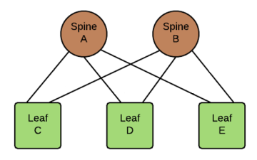
| Figure 34 | Leaf and Spine Configuration |
The configuration steps are as follows:
| • | Configure stack GigaStream. The stack GigaStream connect the spine and leaf nodes. In Figure 2 Stack GigaStream Configuration, the stack GigaStream are: a1, a2, a3, b1, b2, b3, c1, c2, d1, d2, e1, e2. Even if there is only one port that connects the nodes, you must still configure a stack GigaStream. With a configuration of two spine nodes and three leaf nodes, the number of stack GigaStream is 12. |
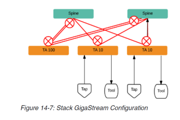
| Figure 35 | Stack GigaStream Configuration |
| • | Configure spine links. On each leaf node, there is one spine link that contains the list of GigaStream connecting the leaf nodes to the spine nodes. The spine links contain multiple stack GigaStream that are bundled together. The spine links are: {c1,c2}, {d1,d2}, and {e1,e2}. The total number of spine links is three for this configuration. The spine links are located at the leaf nodes. Across the spine link members, traffic is load balanced. For this part of the configuration, refer to the circles in Figure 3 Spine Link Configuration. |
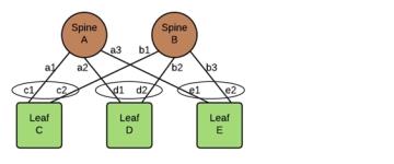
| Figure 36 | Spine Link Configuration |
Note: For the spine links, make sure that all paths are reachable.
| • | Configure stack links. The stack links are: {a1,c1}, {a2,d1}, {a3,e1}, {b1,c2}, {b2, d2}, and {b3, e2}. The total number of stack links is six for this configuration. For this part of the configuration, refer to the circles in Figure 4 Stack Link Configuration. |
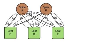
| Figure 37 | Stack Link Configuration |
These configuration steps ensure that the spine and leaf nodes are fully meshed.


